Quick Ra reference for rotating-equipment parts:
| Feature | Typical Ra (µm) | Usual process |
|---|---|---|
| Pump shaft bearing journal | 0.4 – 0.8 | Turning + cylindrical grinding |
| Rotating mechanical seal face | 0.1 – 0.2 | Lapping |
| Stationary mechanical seal face | 0.1 – 0.8 | Lapping or fine grinding |
| Rolling bearing fit (shaft & housing) | 0.4 – 0.8 | Turning + grinding |
| O-ring static groove | 0.8 – 1.6 | Turning |
| O-ring dynamic sealing surface | 0.2 – 0.4 | Grinding or polishing |
The rest of this article explains why these values look the way they do, where buyers most often get them wrong, and how to call them out on a drawing so suppliers don't reinterpret the spec.
When a Correct Drawing Still Produces a Failed Part
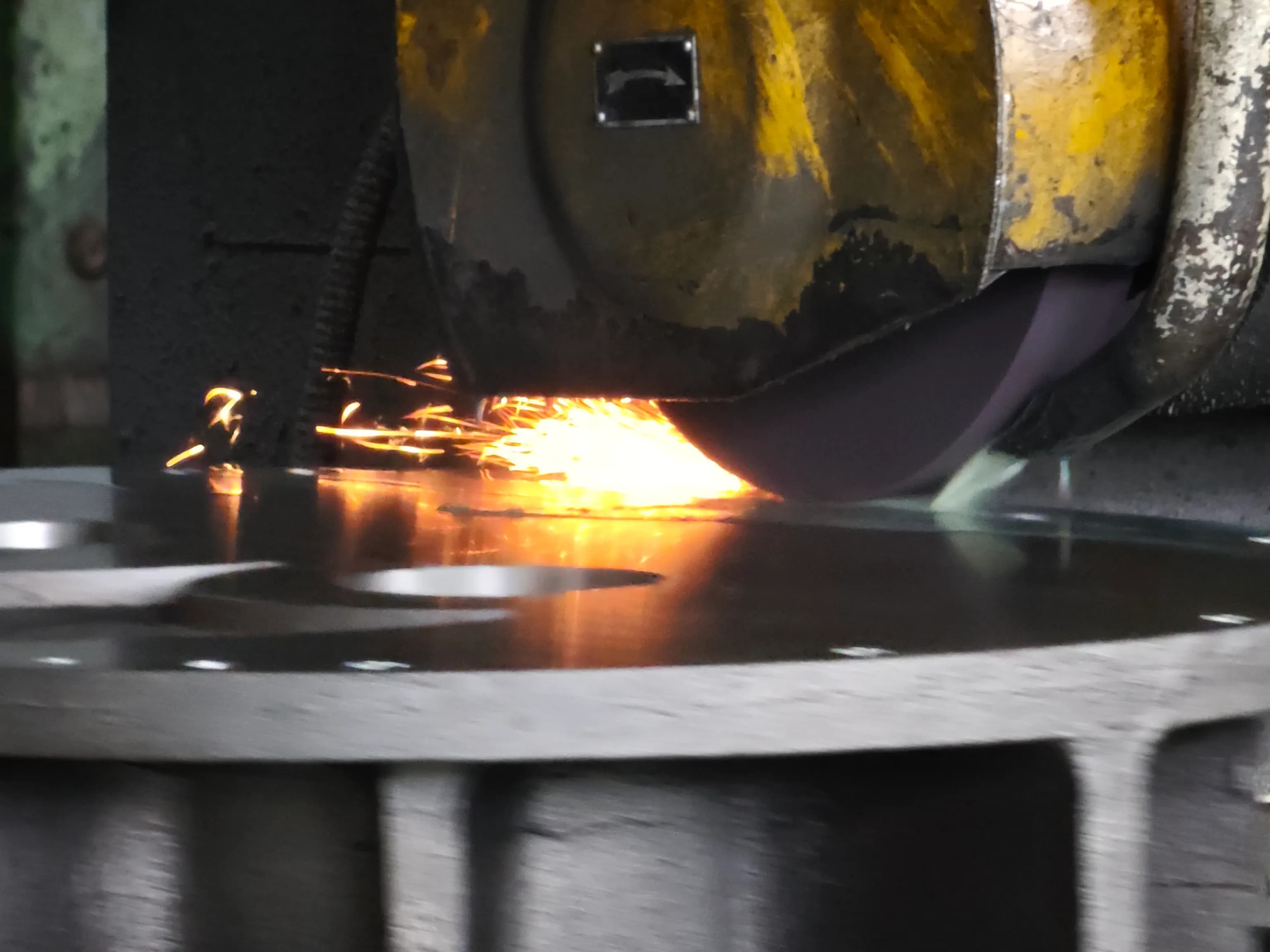
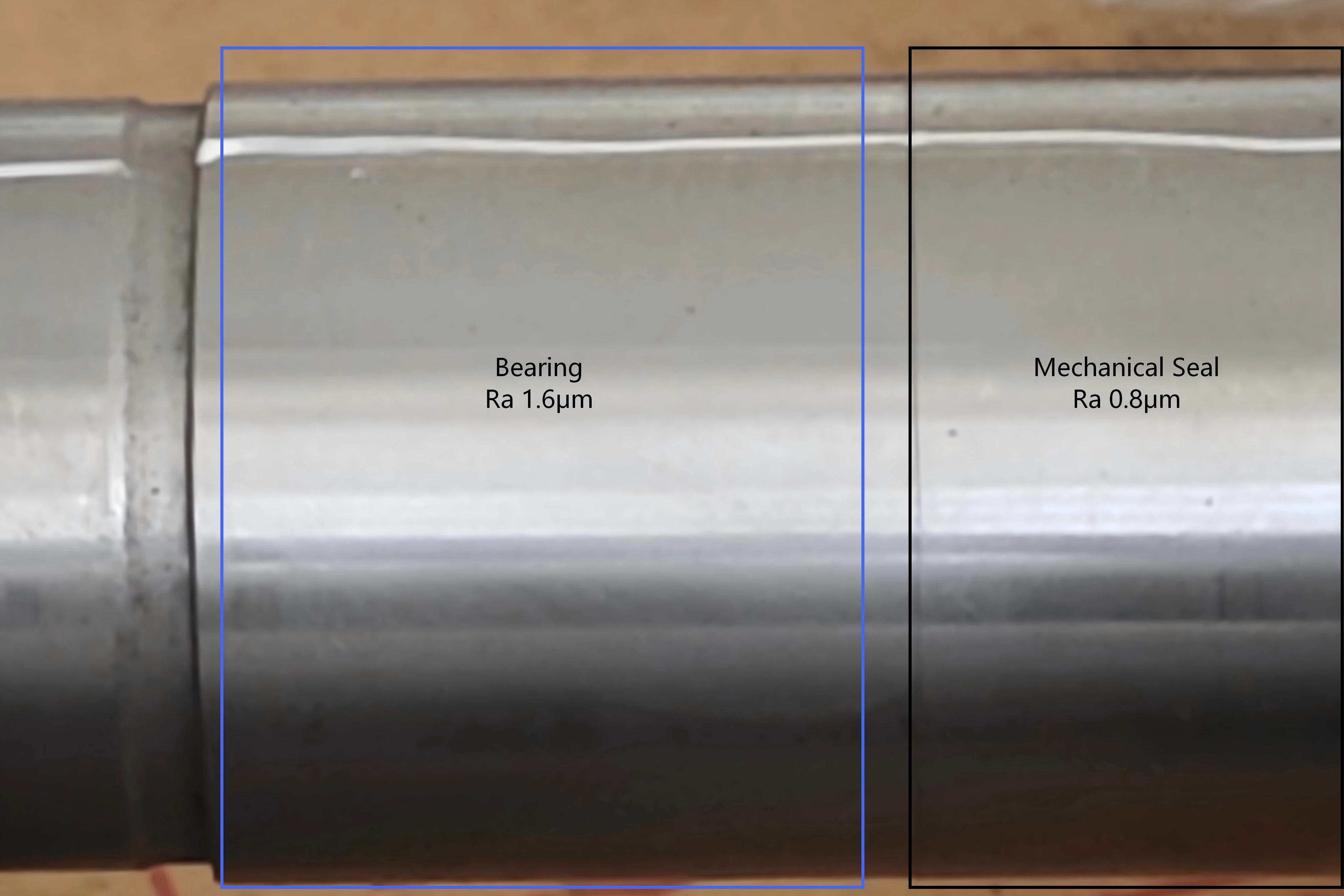
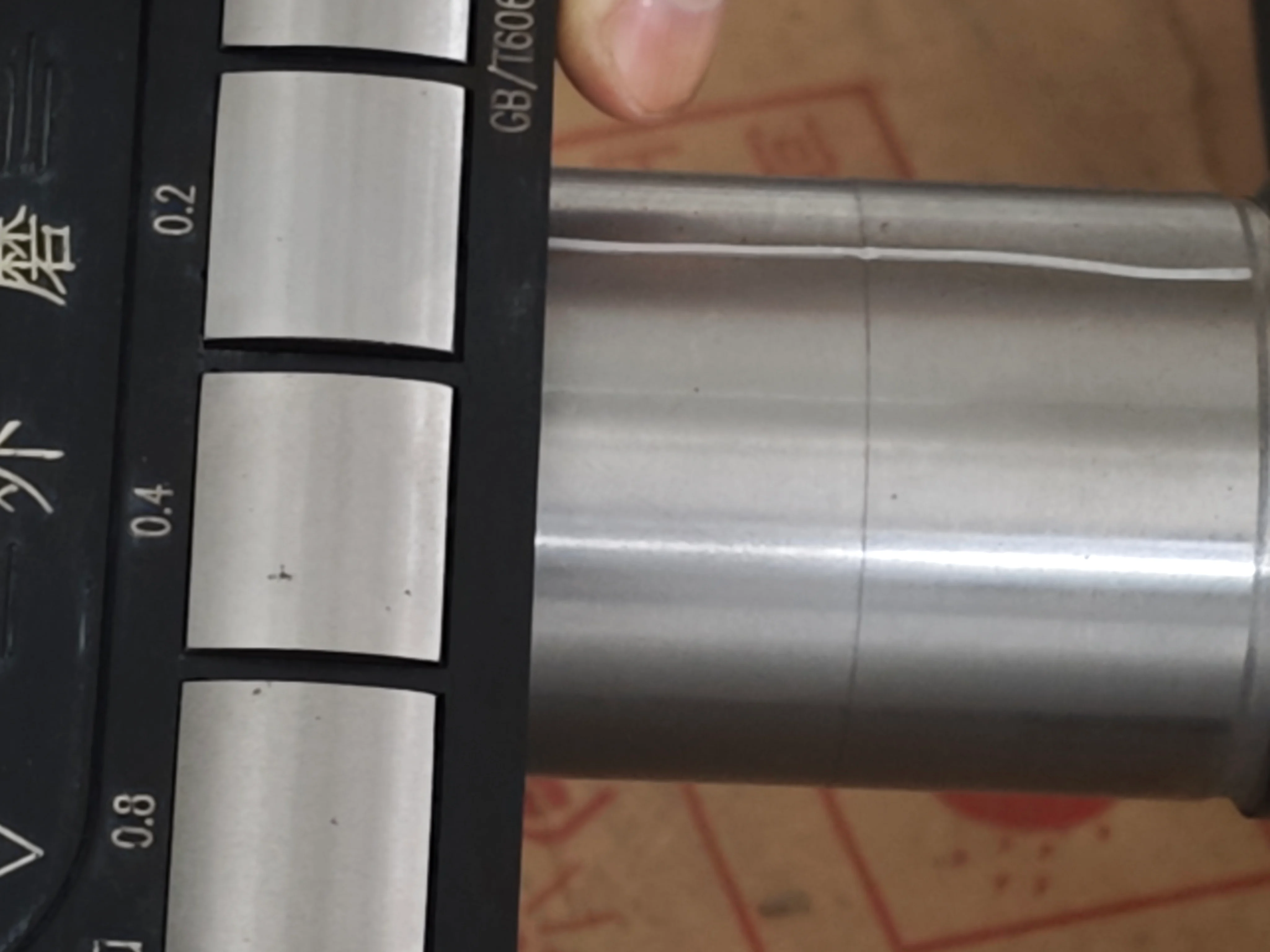
During my second year in the factory, a vacuum pump failed a performance test because of a slow oil leak around the mechanical seal. The first instinct on the shop floor was the same as always: a critical dimension must be wrong. We pulled the assembly drawing, checked every machined part against tolerance, reviewed the inspection records, and confirmed the material certificate. Nothing looked suspicious. Every key dimension was within spec — but the pump still leaked.
The problem traced back to the mechanical seal supplier. Their cylindrical grinder had been down for maintenance, so to keep the order moving they skipped the final grinding pass. The bore surface that contacted the shaft was left as a turned surface at roughly Ra 3.2 µm, while our drawing required Ra ≤ 0.8 µm. Under a pocket light along the contact area, fine machining marks were clearly visible across the seal face. That small difference was enough to cause the failure: the rougher surface prevented a stable lubricating film from forming between the rotating and stationary seal faces. Once the pump ran under load, the surfaces made direct contact, generated heat, and the seal failed within minutes. From the outside the part looked fine; on the inspection report every dimension was correct; in the actual machine, it could not hold pressure.
This kind of problem is easy to miss during procurement. Buyers usually focus on tolerances, material grades, certificates, and delivery time. Surface finish often appears as a small Ra value in the corner of a drawing, a vague note like “smooth surface,” or nothing at all. But for precision machined industrial parts, surface finish is not about appearance — it decides whether a part seals properly, runs smoothly, wears normally, or fails shortly after installation. This article walks through what Ra actually means in industrial machining, where surface finish matters most, and how to specify it on drawings and RFQs so parts arrive ready for real assembly, not just inspection.
Surface finish is also one of the practical reasons CNC machining still dominates for sealing-critical and rotating parts, even as additive manufacturing improves — we cover that trade-off in CNC machining vs 3D printing for industrial parts.
Ra, Rz, Rmax — Why You Should Stop Using Them Interchangeably
The first confusion usually starts with the roughness symbol itself. On many drawings, buyers will see a simple Ra value and assume the requirement is clear. But surface roughness is not described by only one universal number. Different regions, industries, and drawing standards may use different parameters, and they do not convert neatly into one another.
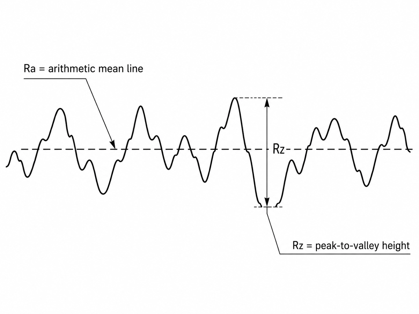
Ra is the most common one. It represents the average roughness of a surface profile, so it gives a general picture of how smooth or rough the surface is overall. This is why Ra appears so often on industrial drawings in China, the United States, and much of Europe. But Ra has one important limitation: it is an average. A surface can have a good Ra value and still contain a deep scratch or a sharp local peak that causes sealing or wear problems.
That is where Rz becomes useful. Rz looks at the height difference between peaks and valleys over several sampling lengths, so it gives more attention to the actual profile height of the surface. German and Japanese drawings often use Rz more frequently than Ra.
Rmax, sometimes shown as Rt, goes one step further. It focuses on the largest single peak-to-valley distance over the evaluation length. This matters when one local defect, scratch, or machining mark can create a functional problem.
For general machining work, Ra is usually enough to communicate the finish requirement. But for sealing faces, sliding surfaces, bearing seats, or other critical contact areas, relying only on Ra can sometimes hide problems that matter in the real assembly.
One mistake we still see on imported drawings is treating Ra and Rz as if they were the same thing. They are not. For a normal machined surface, Rz is usually several times larger than Ra. A rough rule of thumb is that Rz may be around 4 to 7 times the Ra value, depending on the material, cutting method, tool condition, and finishing process. So if a drawing says Ra 0.8 µm, it should not be casually rewritten as Rz 0.8 µm just because the number looks similar.
That small mistake can completely change the manufacturing requirement. Rz 0.8 µm is a much stricter surface than Ra 0.8 µm in most practical machining situations. The part may still be manufacturable, but it will likely require more grinding, polishing, inspection time, and cost than the original design intended. There are also two details that are easy to overlook when reading surface finish requirements.
The first is cut-off length, usually written as λc. This is the filtering length used during roughness measurement. For many general machined surfaces, the common default is 0.8 mm. For very smooth ground or lapped surfaces, a shorter cut-off such as 0.25 mm may be more suitable.
The second is measurement direction. A machined surface has a lay, or a visible direction left by the cutting tool or grinding process. If roughness is measured across the tool marks, the result can look much worse than if it is measured along the same marks. This can create real disagreement between buyer and supplier. The supplier may believe the part passes inspection, while the buyer measures in a different direction and gets a different result.
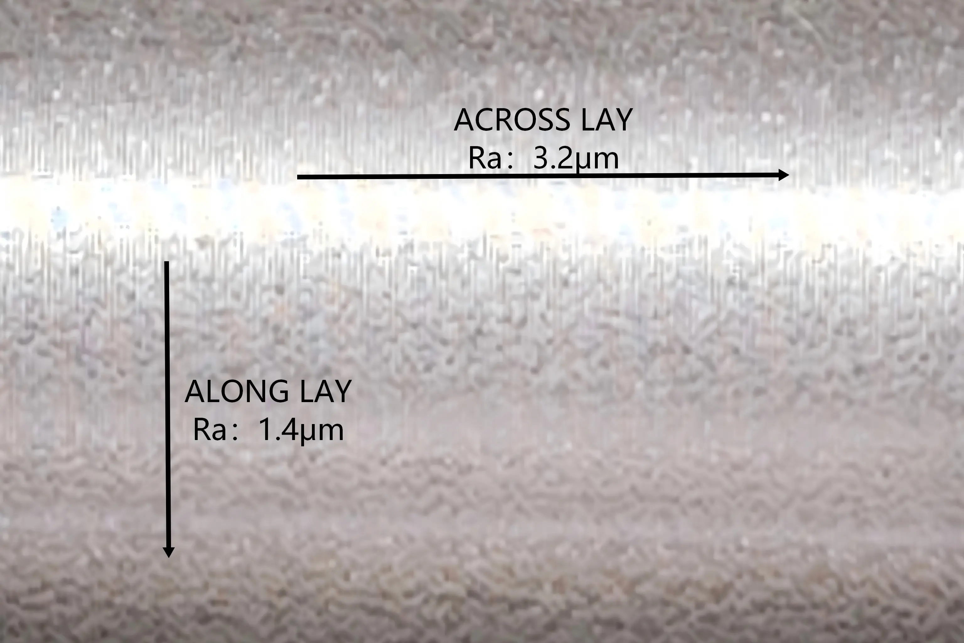
For general brackets or structural parts, these details may not matter much. But for sealing surfaces, bearing journals, shaft contact areas, sliding surfaces, and any feature that works against a moving mating part, these small measurement details can decide whether the component performs correctly after assembly.
What Ra Actually Controls in a Working Assembly
Surface finish is not a decorative specification. In many precision machined industrial parts, the Ra value affects how two surfaces contact each other, how they move, how they seal, and how long they can keep working before wear begins to show. This is why surface finish should not be treated as a small note on the drawing. For certain features, it is part of the function of the part itself.
1. Friction and Wear
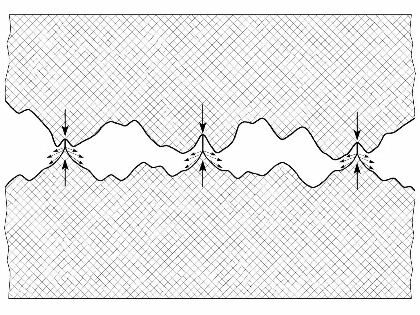
Under a microscope, a machined surface is not truly flat or smooth. It is made up of tiny peaks and valleys left by turning, milling, grinding, or polishing. When two parts slide or rotate against each other, the load is not carried by the full contact area shown on the drawing. In reality, the first contact happens at those microscopic peaks. If the surface is too rough, fewer high points carry more of the load. That creates higher local stress, more friction heat, and faster wear. This matters for shafts, sleeves, bushings, sliding faces, guide surfaces, and many other moving or contact features.
For example, when a pump shaft runs inside a bushing or seal, the early running period is partly a process of the surface peaks wearing down until the contact becomes more stable. If the starting surface is too rough, that run-in stage can produce debris and scratch the mating surface before the system has a chance to settle.
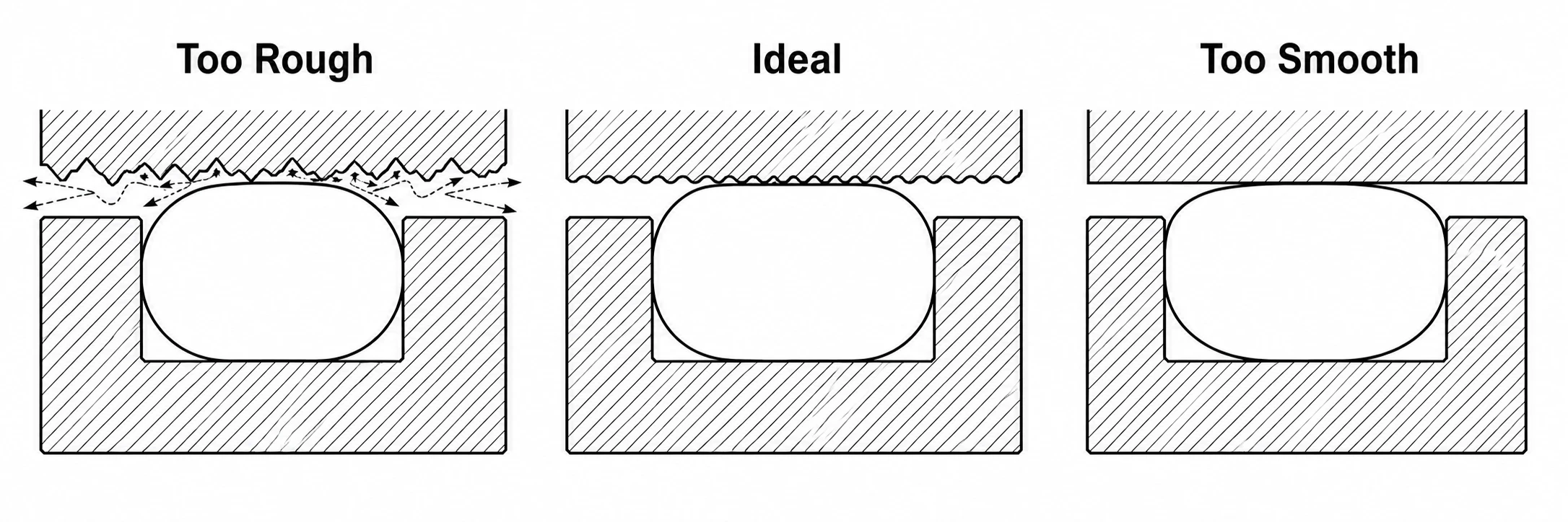
But the opposite can also become a problem. A surface that is too smooth may not retain enough lubricant, depending on the working condition and sealing method. In that case, the part may lose the thin oil film it depends on, and the failure mode changes from abrasive wear to poor lubrication. So the goal is not always the lowest possible Ra value. The goal is the right Ra value for the way the surface actually works.
2. Sealing Performance
Sealing is one of the areas where surface finish shows its effect very quickly.
For a static seal, such as an O-ring sitting in a machined groove, the finish of the groove and mating surface directly affects how well the elastomer can seat and block leakage. If the surface is too rough, the seal may not be able to follow the valleys, leaving small leak paths. If the surface is too smooth in the wrong application, the elastomer may not seat as reliably as expected. For many static O-ring sealing surfaces, a practical finish range is often around Ra 0.4 to Ra 1.6 µm, depending on the material, pressure, seal design, and working environment.
dynamic seal are much less forgiving. In a mechanical seal, the system depends on a very thin lubricating film between the rotating and stationary seal faces. Those faces are not simply “touching” each other in the ordinary sense. They need a controlled surface condition that allows the film to form and remain stable during operation. For this kind of application, the required finish is usually much finer than a general turned or milled surface. A surface that might look acceptable on a normal machined part can be completely unsuitable for a mechanical seal.
That is exactly the failure mode that started this article. The part looked correct. The dimensions were within tolerance. But the seal contact surface had been left with a rough turned finish instead of the required fine ground finish. Once the pump started running, the lubricating film could not form properly, friction heat built up, and the seal failed within minutes. This is why surface finish matters so much on sealing features. The part does not fail because it looks rough. It fails because the surface can no longer support the physical function it was designed for.
3. Fatigue Life
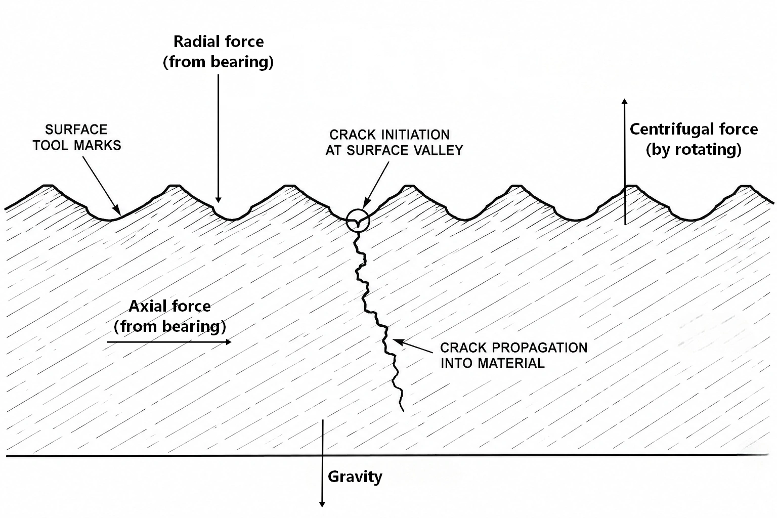
Surface finish also affects fatigue life, especially on parts that experience repeated loading.
A machined surface is never perfectly smooth. Every small peak, valley, scratch, or tool mark can become a local stress concentration. Under static loading, this may not cause any immediate problem. But under cyclic loading, those small surface features can become the starting points for fatigue cracks. This matters for rotating shafts, reciprocating components, bearing journals, sleeves, and other parts that operate under repeated stress.
For a shaft running at high speed, the difference between a controlled ground surface and a rough turned surface is not only visual. A rougher surface can increase local stress, accelerate crack initiation, and reduce service life over time. This is why some high-duty industries do not look at surface finish alone. They use the broader term “surface integrity,” which may include roughness, residual stress, grinding burn, microcracks, hardness changes, and other surface-layer conditions.
In other words, the surface is not just the outside of the part. In fatigue-critical applications, it is often where failure begins.
4. Interference and Transition Fits
Surface finish also affects press fits, bearing fits, and other interference or transition fits.
On a drawing, an interference fit looks like a simple dimensional relationship between a shaft and a bore. But during assembly, the two parts contact each other through real machined surfaces, not ideal geometry. The microscopic peaks on both mating surfaces are partially flattened during press-in. Because of this, the effective interference after assembly can be slightly different from the theoretical interference shown on the drawing. For large or low-precision parts, this small difference may not matter much. But for small bearing seats, precision shafts, and high-load fits, it can affect holding force and long-term stability.
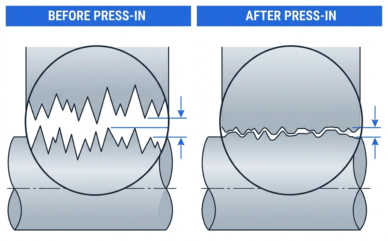
This is why bearing seats and shaft journals often need both dimensional tolerance and surface finish control. The tolerance defines the size. The surface finish helps define how that size behaves once the parts are actually assembled. A shaft that is dimensionally correct but too rough may not give the same fit behavior as a properly finished shaft. Under load, vibration, or repeated start-stop conditions, that difference can become important. For our own CNC milling, we try to keep functional surfaces predictable before any final grinding, polishing, or coating step begins. A stable machined finish gives the next process a better starting point and reduces the chance of chasing variation from rough machining.
A Practical Ra Reference Table for Rotating Equipment Parts
Surface finish requirements should always come from the part’s real function. A sealing face, a bearing seat, a shaft surface, and a general mounting face should not be specified the same way.
The table below is not a universal standard. It is a practical reference based on common industrial machining applications we often see in pump components, compressor parts, shafts, housings, sealing areas, and general engineered metal parts.
For critical components, the final Ra requirement should always be confirmed with the design engineer, seal supplier, bearing manufacturer, or assembly engineer.
| Part / Feature | Function | Recommended Ra (µm) | Common Process |
|---|---|---|---|
| Pump shaft — bearing | rolling contact, oil film | 0.8 – 1.6 | Turn + Grind |
| Pump shaft — coupling end | Press fit / keyway | 1.6 – 3.2 | Turn |
| Mechanical seal face (rotating) | Hydrodynamic film | 0.1 – 0.2 | Lap / Polish |
| Mechanical seal face (stationary) | Mating with rotor | 0.1 – 0.8 | Grind + Lap |
| Bearing housing bore | Press fit OD | 0.8 – 1.6 | Bore + Grind |
| O-ring groove (static) | Elastomer seal | 0.4 – 1.6 | Mill / Turn |
| Sealing flange (gasket) | Gasket seating | 1.6 – 3.2 | Mill |
| Hydraulic cylinder bore | Piston seal sliding | 0.2 – 0.4 | Hone |
| Gear tooth flank | Mesh contact | 0.4 – 0.8 | Grind / Shave |
| Impeller / rotor blade | Fluid efficiency | 1.6 – 3.2 | Mill / Polish |
| Threaded surface (general) | Fastening | 3.2 – 6.3 | Turn / Tap |
A few notes that don't fit neatly into the table:
For sealing surfaces, smoother is not always better. Most people understand that a rough surface can cause leakage. What is easier to miss is that some sealing systems also need a controlled surface texture to support lubrication, gasket seating, or elastomer contact. For mechanical seals especially, the target is usually a specific working range, not simply “as smooth as possible.”
Bearing seats should also be checked together with the bearing manufacturer’s recommendation. Companies such as SKF, NSK, FAG, and other bearing suppliers often provide recommended shaft and housing surface finishes for different bearing types and operating conditions. A general machining table is useful for early discussion, but it should not replace the bearing supplier’s data for critical assemblies.
Gasket sealing faces are another area where drawings are sometimes over-specified. A general gasket flange does not always need a very fine ground finish. In many cases, flatness, gasket material, bolt load, and surface consistency matter more than chasing an unnecessarily low Ra value. If every flange face on a drawing is marked with a strict surface finish, the part may become more expensive without improving its real sealing performance.
At SCPM, many functional surfaces are finished through controlled CNC finishing, cylindrical grinding, surface grinding, or additional polishing when required. For suitable steel components, we can support fine finishes such as Ra 1.6 and below depending on the material, geometry, and application.
How to Specify Ra Correctly on a Drawing or RFQ
The technical knowledge above only helps if it is written clearly on the drawing or RFQ.
Surface finish callouts are one of the easiest areas for misunderstanding. We still see drawings that use different roughness symbols, different standards, or old callout styles. Sometimes the Ra value is marked clearly. Sometimes it is hidden in a general note. Sometimes the drawing says “smooth finish,” which leaves too much room for interpretation.
For simple structural parts, that may not cause a serious problem. For precision machined parts with sealing faces, bearing fits, sliding surfaces, coated areas, or moving contact features, unclear surface finish requirements can lead to real assembly issues. A good RFQ should make the surface finish requirement easy for the supplier to understand and inspect.
Current Drawing Standards
Surface finish symbols are not always written the same way on every drawing. Some drawings follow ISO standards. Some follow ASME standards. Some older drawings still use symbols or notes from previous revisions. In international machining work, it is common to receive drawings from different countries that use slightly different surface finish callouts.
Today, many new international drawings are moving toward ISO 21920, which replaced the older ISO 1302 series. American drawings may use ASME Y14.36 or similar surface texture notation. The symbols are usually understandable to an experienced machining supplier, but mixing different systems on the same drawing can still create confusion during inspection.
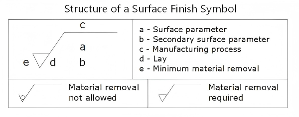
In most cases, the roughness value is written directly with the parameter name, such as Ra 0.8 or Rz 6.3. The value is normally given in micrometers. For general machined surfaces, this may be enough. For critical surfaces, it is better to write the requirement more clearly. That may include the roughness parameter, the target value, the required process if needed, the cut-off length, and the measurement direction.
For example, a general note such as “smooth finish” is too vague. Even a note like “Ra 0.8” may not be enough if the surface is a sealing face, bearing seat, shaft journal, or sliding contact area. A clearer callout helps both sides. The supplier knows what process and inspection method to use, and the buyer has a more reliable way to judge whether the part actually meets the design intent.
Three Surface Finish Mistakes I Have Seen in Real Production
Most surface finish problems do not start at the inspection stage. They usually begin much earlier, when the drawing does not clearly explain which surfaces are truly functional. During my work, I have seen three mistakes appear more than once.
1. One Ra Value Applied to the Whole Part
A general note such as “all surfaces Ra 1.6 unless otherwise specified” may look clean on a drawing, but it often creates confusion in production.
For the supplier, it is not always clear whether every surface really needs Ra 1.6, or whether only the functional surfaces need that finish. If every face is treated as critical, machining time and cost increase. If the machinist assumes only certain surfaces matter, there is a risk that the buyer or inspector expected something different.
A better approach is to separate general surfaces from functional surfaces. For non-critical areas, a normal machined finish is usually enough. Tighter Ra values should be applied only to surfaces that affect fit, sealing, sliding contact, coating, fatigue life, or assembly accuracy.
2. No Measurement Direction on Directional Surfaces
Many machined surfaces have a clear lay, or tool mark direction. A turned shaft journal, for example, does not have the same surface texture in every direction. Roughness measured along the tool marks can be different from roughness measured across them. If the drawing does not specify the measurement direction for a critical surface, both sides may believe they are measuring correctly but still get different results. For general surfaces, this may not matter much. But for shaft journals, sealing areas, sliding surfaces, and precision contact features, measurement direction should be clarified before production.
3. Tight Ra on Features That Do Not Need It
Another mistake is specifying a very fine surface finish on surfaces that have no real functional reason for it. For example, the outside face of a bracket, cover, or general mounting part may not need Ra 0.8 if it does not seal, slide, locate, or carry a precision fit. Requiring a fine finish on every surface adds machining time, tool wear, inspection work, and cost.
This does not necessarily make the part better. It only makes the part more expensive. Tight surface finish requirements should be reserved for surfaces where the finish actually affects performance: sealing faces, bearing fits, shaft journals, sliding surfaces, fatigue-loaded areas, and precision contact features. For everything else, a normal machined finish is usually the more practical choice.
What to Ask Your Supplier Before You Place the Order
Before placing an order, buyers do not need to ask dozens of technical questions about surface finish. A few simple questions are usually enough to understand whether the supplier has real control over the process.
The first question is:
What surface finish do you normally achieve if the drawing does not specify an Ra value?
A reliable shop should be able to give a practical answer based on the machining process, material, and feature type. Turning, milling, grinding, and polishing do not produce the same finish, so a vague answer such as “we make it smooth” is usually not enough.
The second question is:
Can you measure Ra on the critical features if needed?
Not every surface needs a roughness report. But for sealing faces, bearing fits, shaft journals, sliding surfaces, and coated functional areas, the supplier should be able to measure and confirm the surface finish instead of relying only on visual inspection.
The third question is:
How do you handle surfaces without explicit finish callouts?
This is where many misunderstandings happen. If the drawing does not clearly mark every surface, the supplier needs a consistent internal approach. Otherwise, the final result may depend too much on the individual operator, tool condition, or machining setup.
At SCPM, we review surface finish requirements together with the part function, material, tolerance, and manufacturing route. When a drawing includes specific Ra requirements, we identify the critical features before production and choose suitable machining, grinding, or finishing steps accordingly.
For functional steel, stainless steel, and cast iron components, we can provide surface roughness inspection on request and include the result with the dimensional inspection report when required.
Once the drawing separates critical Ra surfaces from general machined faces, we usually decide the process route next. Precision grinding handles shaft journals, sealing faces, bearing seats, and other tight-contact features. Surface finishing coordination becomes part of the plan when passivation, plating, coating thickness, polishing, or bead blasting can change the final surface that the drawing controls.
If you are not sure whether your drawing is over-specifying or under-specifying surface finish, you can send it to us for review. We can help identify which surfaces truly need tighter Ra control and which areas can use a more practical machined finish before quoting.
One Often-Missed Point: Lower Ra Is Not Always Better
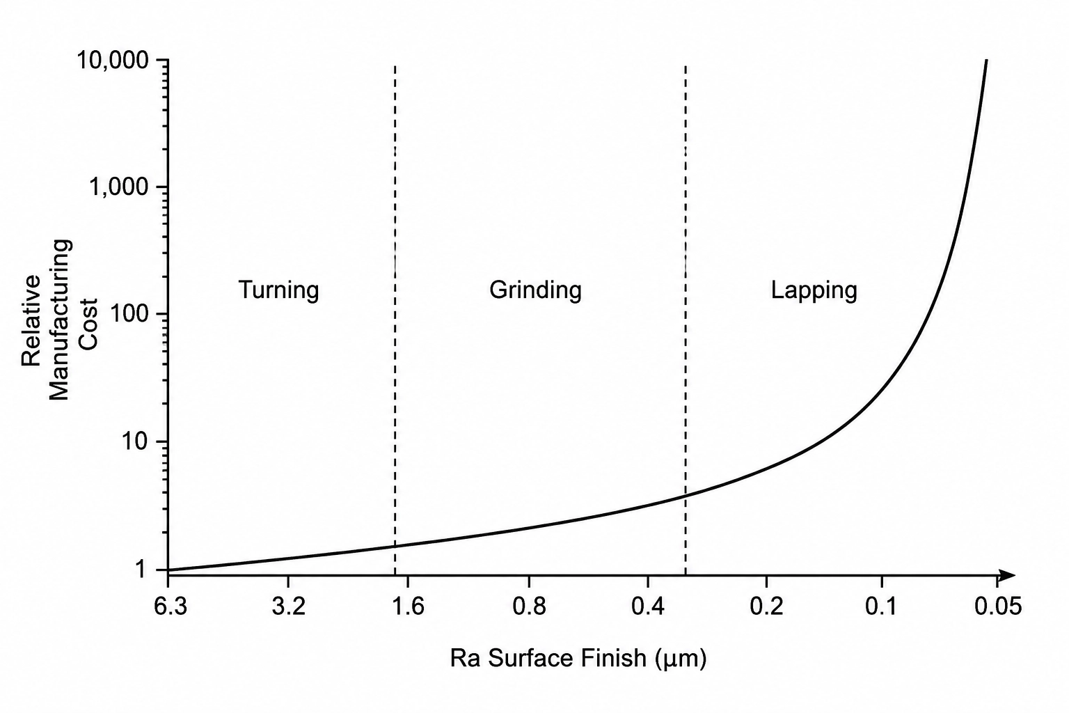
A common misunderstanding is that a lower Ra value always means a better part. In some cases, a smoother surface does improve performance. But that does not mean every surface should be pushed to the lowest possible Ra value. Surface finish should be decided by function, not by the idea that “smoother is always better.” A tighter Ra requirement usually brings three practical consequences.
The first is higher manufacturing cost. Going from a normal machined finish to a finer finish may require slower cutting, a sharper tool, an additional finishing pass, grinding, polishing, or more careful inspection. The closer the requirement gets to a very fine surface, the more likely it is that a separate finishing operation will be needed.
The second is longer lead time. Every additional finishing step adds setup time, inspection time, and movement between processes. For a simple part, this may not change the schedule much. But for parts with multiple critical surfaces, unnecessary fine finish requirements can slow down the entire production route.
The third is that performance does not always improve. Some sealing surfaces, sliding surfaces, and lubricated contact areas are designed to work within a certain surface texture range. If the surface is too rough, leakage or wear may occur. But if the surface is made too smooth for the application, lubrication, gasket seating, or run-in behavior may also become less stable.
This is why the best surface finish is not always the lowest number.
The practical rule for buyers is simple: specify Ra based on what each feature does. A sealing face, a bearing seat, a shaft journal, a sliding surface, and a general exterior surface should not all carry the same finish requirement. If only two surfaces are functional, those two surfaces should be controlled carefully. The rest can often use a normal machined finish.
A good machining supplier should not only accept the drawing blindly. When a surface finish appears over-specified or unclear, they should be willing to ask questions and help separate truly critical surfaces from general surfaces. That discussion can reduce cost, shorten lead time, and make the final part more practical for real assembly.
Surface Finish Is Part of the Drawing, Not a Footnote
Looking back at that vacuum pump in the test cell, the failure was not caused by one dramatic mistake.
The material was correct. The main dimensions were within tolerance. The assembly looked normal from the outside. But one surface had not been finished to the level required for the seal to work. That was enough to stop the pump from holding pressure. This is the lesson I took from that failure: in precision industrial assemblies, surface finish is not a small note at the edge of the drawing. For certain features, it carries the same importance as tolerance, material, heat treatment, and assembly clearance. The problem is that surface finish often receives attention only after something has already gone wrong.
For buyers and engineers, there are three practical points worth remembering.
First, specify surface finish on functional features individually, not only as one blanket note for the whole part. A sealing face, bearing seat, shaft journal, sliding surface, and general exterior surface should not all be treated the same way.
Second, use general Ra reference values only as a starting point. The final requirement should still match the real application, mating part, seal type, bearing recommendation, coating requirement, and working environment.
Third, discuss surface finish before production begins. Ask your supplier how they handle unmarked surfaces, whether they can inspect critical Ra values when needed, and which process they plan to use for the most important features.
A small note on the drawing can prevent a large problem in assembly.
If you are sourcing precision machined steel, stainless steel, or cast iron components and are unsure what surface finish to specify, send us your drawing and application requirements. We can review the critical features and help you choose a practical machining and finishing approach before quoting.
Share your thought
Your email is kept private and only used to notify you of replies.