Dry Screw Vacuum Pump Housings
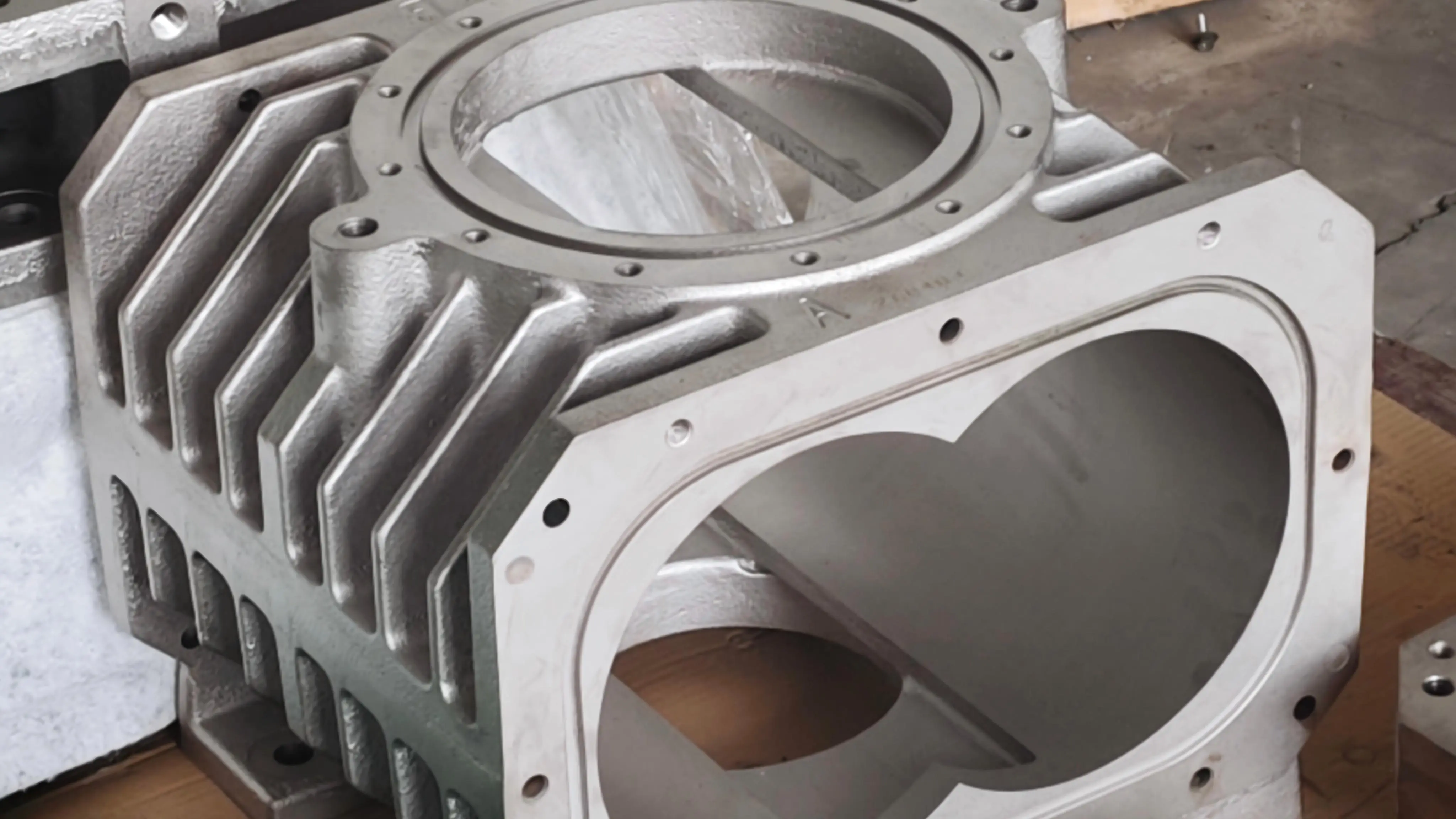
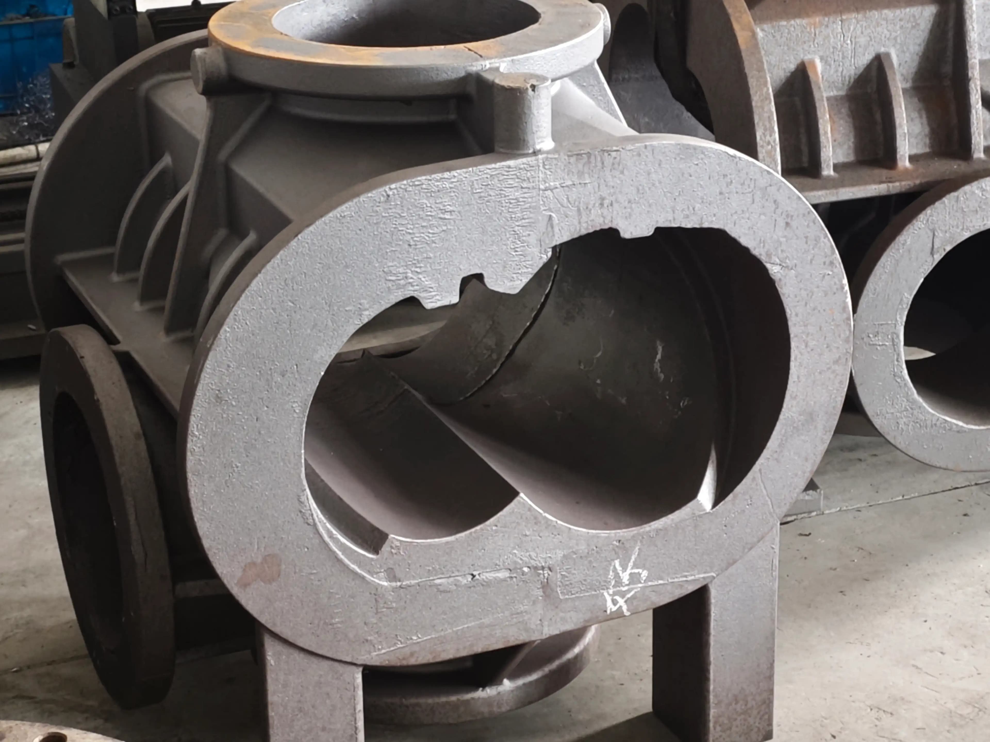
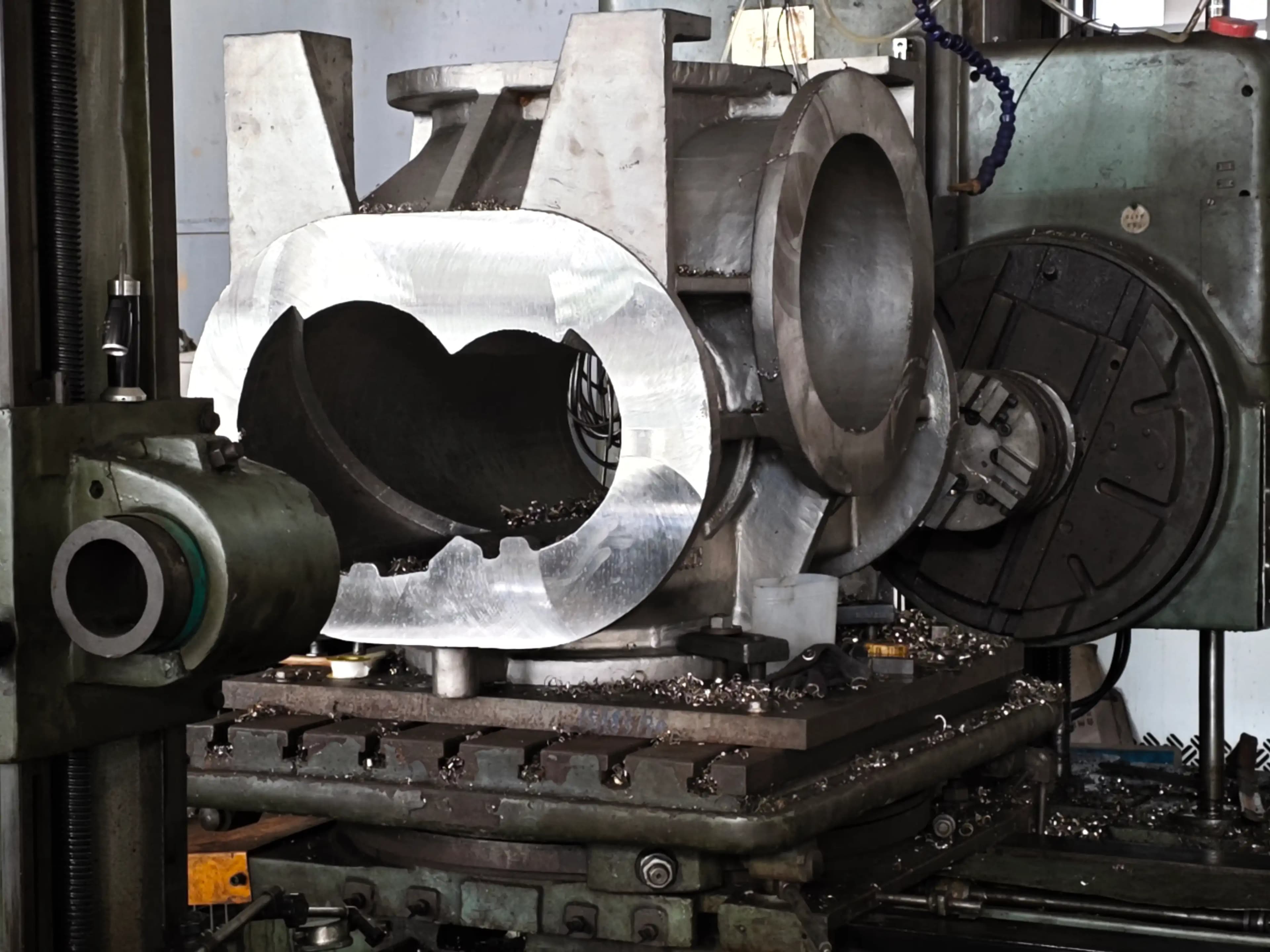
We machine dry screw pump housings for OEM and aftermarket buyers. Both bores are machined in one fixture, on one datum — that's what holds parallelism across a production run, not just on the first piece.
In a dry screw vacuum pump, the fit between housing bore and rotor OD is one of the most important reasons that decides how the pump performs. A few 0.01 mm of extra clearance is enough to destroy the design number — either the pump misses its rated ultimate, or power consumption climbs above the spec.
Bore surface finish matters for the same reason: some shops can't reach the full bore length with the boring bar in one pass, so the housing has to come off the table and get flipped to finish the other half. That leaves a witness mark where the two passes meet — a small ridge sitting in the rotor's running path. Design clearance is already tight, and once the rotor reaches running temperature and grows into its operating diameter, that ridge is where it rubs.
Dowel pin holes are a feature buyers don't usually look at twice. On housings where the bore body and the end plate are separate parts, the dowels hold the end plate aligned to the bore. If the end plate sits a few 0.01 mm off, the rotor lands in the wrong place. The clearance you spec'd on the drawing isn't what's on the pump.
At SCPM, we machine these housings against the drawing and against what we've seen go wrong on pumps built with them. The part you receive will meet the print and won't be the reason the pump misses spec.
Capability Snapshot
Dry Screw Vacuum Pump Housings — specs at a glance
Bore diameter range
Ø70 – Ø400 mm
Housing length
up to 2,000 mm
Twin-bore parallelism
≤ 0.02 mm typical
Bore surface finish (Ra)
0.8 µm finish-bored
Single-setup boring
Both bores finished in one fixture on the 4-axis HMC
Materials
Carbon steel (A36, 1045), Stainless steel (304, 316), Ductile iron (Class 35, Grade 65-45-12)
Pilot route options
Lost-foam cast or welded fabrication
Typical lead time
Confirmed per quote — varies with size, casting lead, and batch
Drawing Commitments
What we commit to on your drawing
The commitments below are what we hold against the GD&T callouts on a typical dry screw vacuum pump housings drawing. Send your drawing for any callout outside this set — we will tell you whether we can hold it before you commit.
| Drawing element | Our commitment |
|---|---|
| Twin-bore parallelism (per ISO 1101) | ≤ 0.02 mm typical; 0.01 mm on tight-clearance designs where the rotor/bore budget supports it |
| Bore Ø tolerance on critical features | ±0.01 mm achievable on the finish pass; coarser fits to drawing |
| Bore surface finish (Ra) | 0.8 µm finish-bored — tighter Ra on request |
| End-cover sealing face (when ground) | Flatness 0.002 mm, Ra 0.4 µm |
| Hardness verification (post heat treatment) | Up to 65 HRC |
| Bore-to-bore centre distance | Up to 238 mm machined to date; upper limit depends on the housing's machine-design envelope |
| Dowel position / mount-feet positional tolerance | Held to the print — GD&T target set by your drawing, not a house default |
Test Orders
Try the machining before you pay for a casting pattern.
Option 1
Cast Prototype
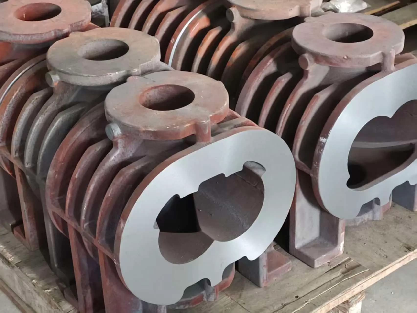
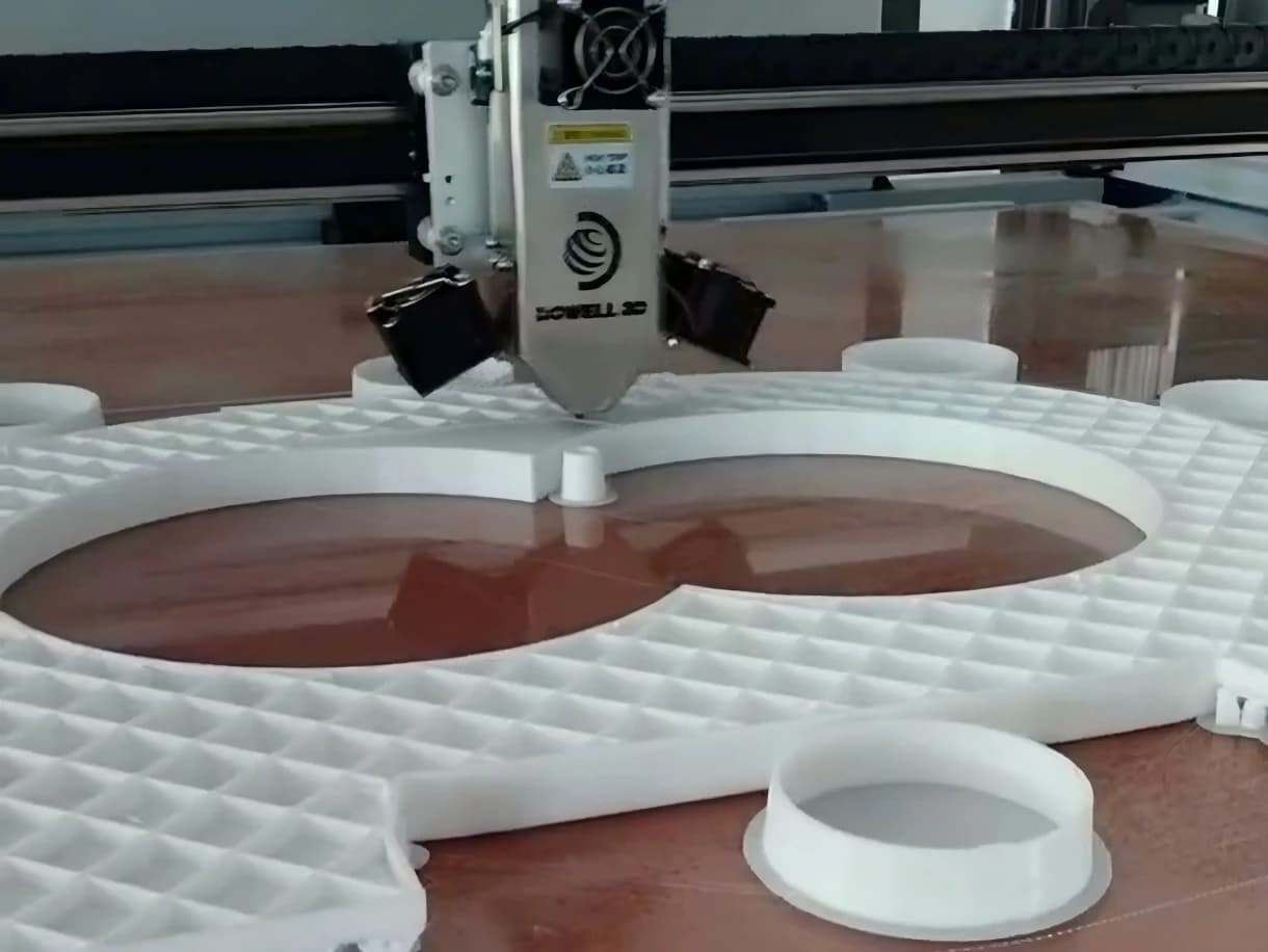
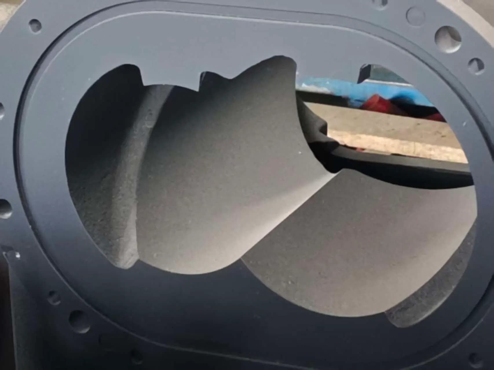
The standard route when you're going to series production. A partner shop 3D-prints a foam pattern of the housing, cast it through a lost-foam process, then bring the casting back to our floor for final machining.
Option 2
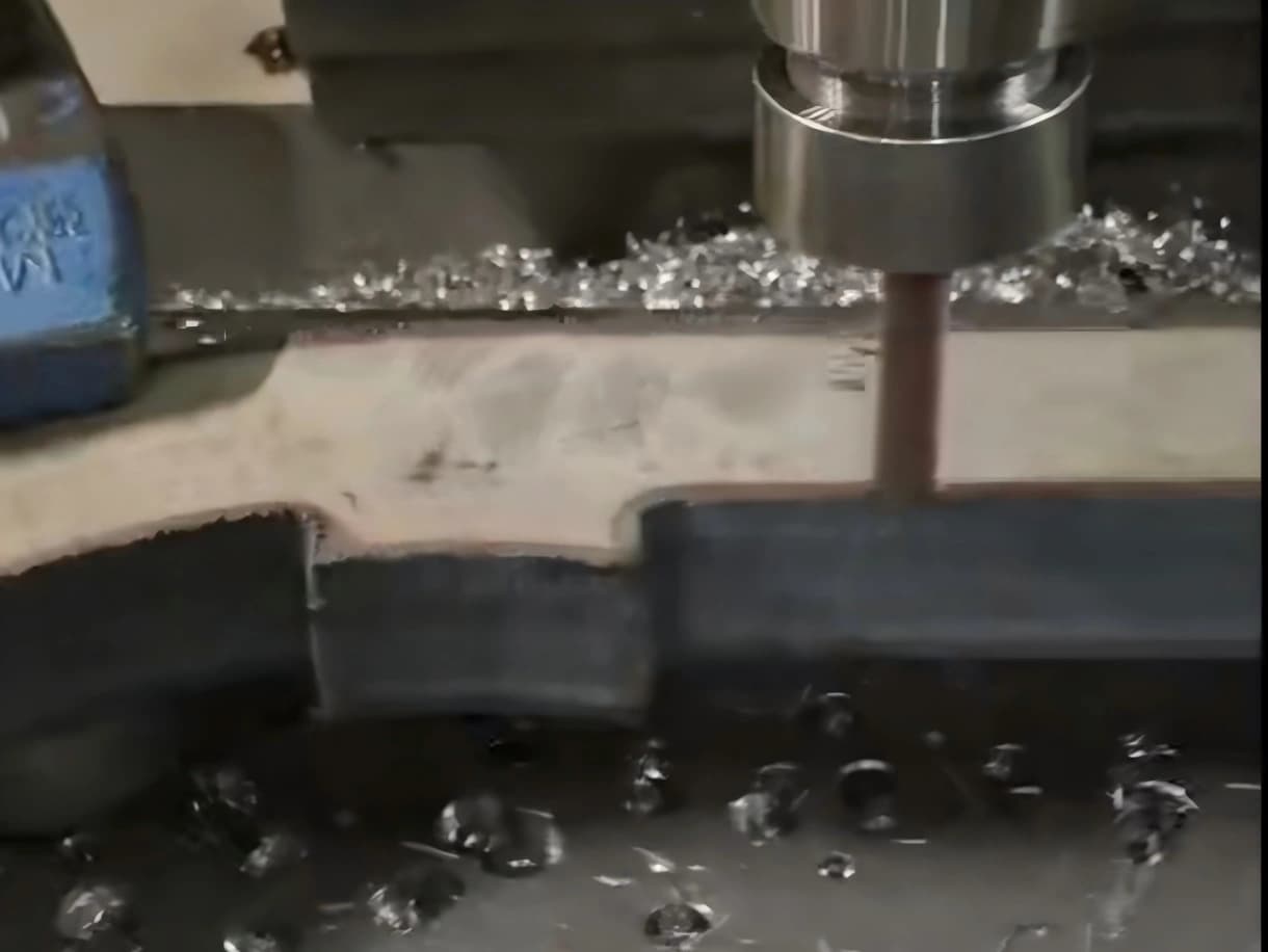
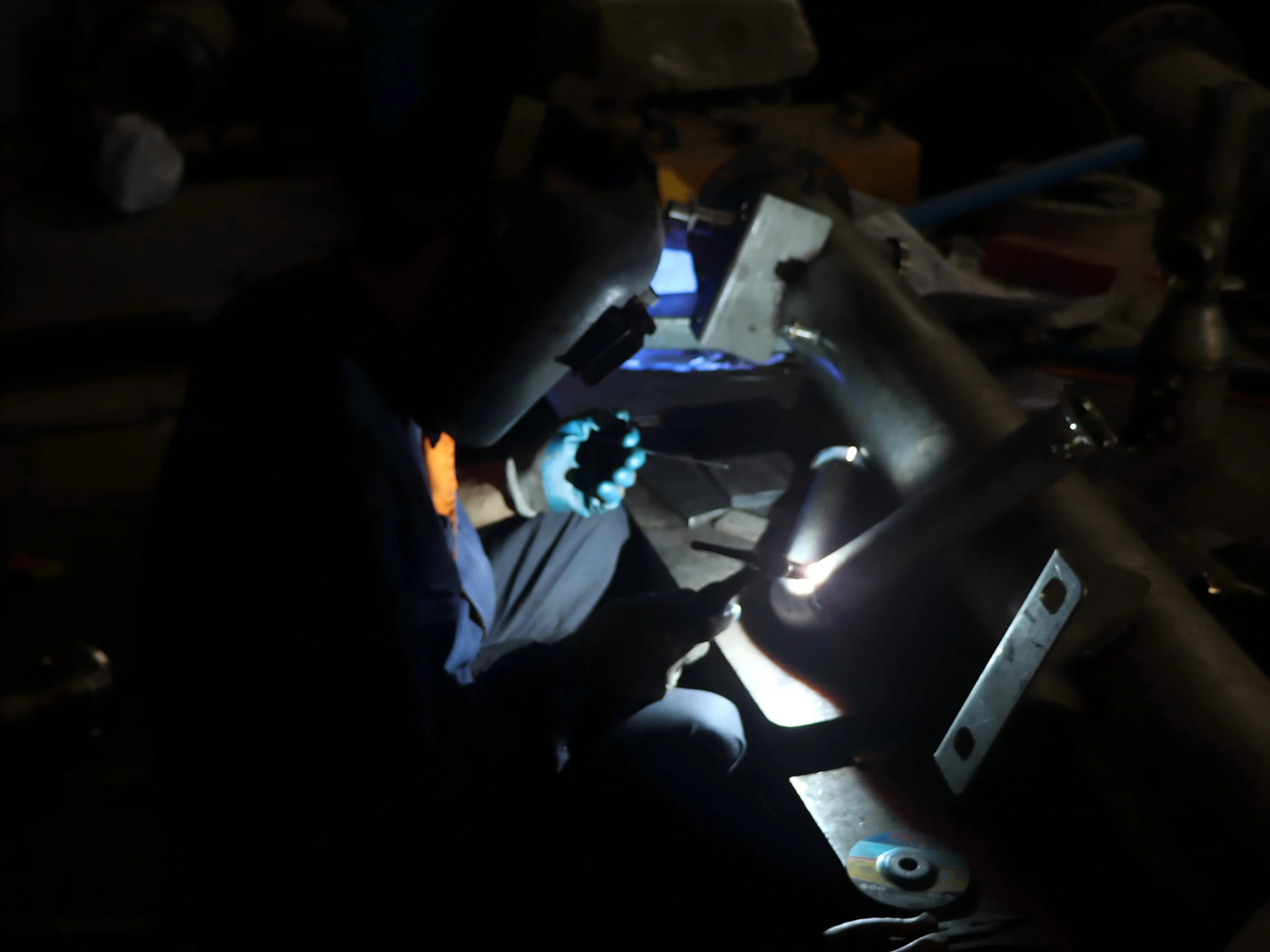
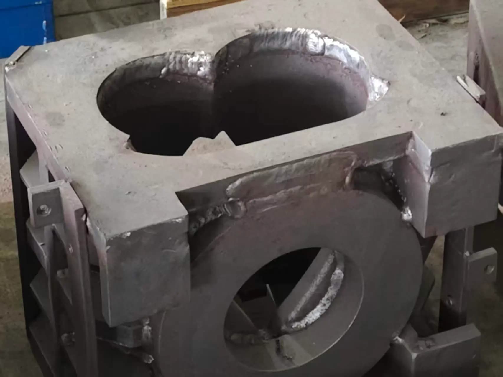
Weld Prototype
We break the housing into sections, machine each piece from solid stock, and weld them into a housing. Machining and finishing process will be applied, and it is qualified for a final production.
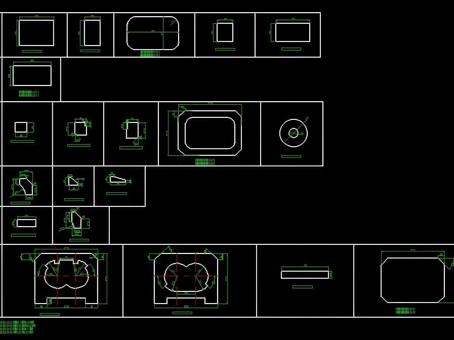
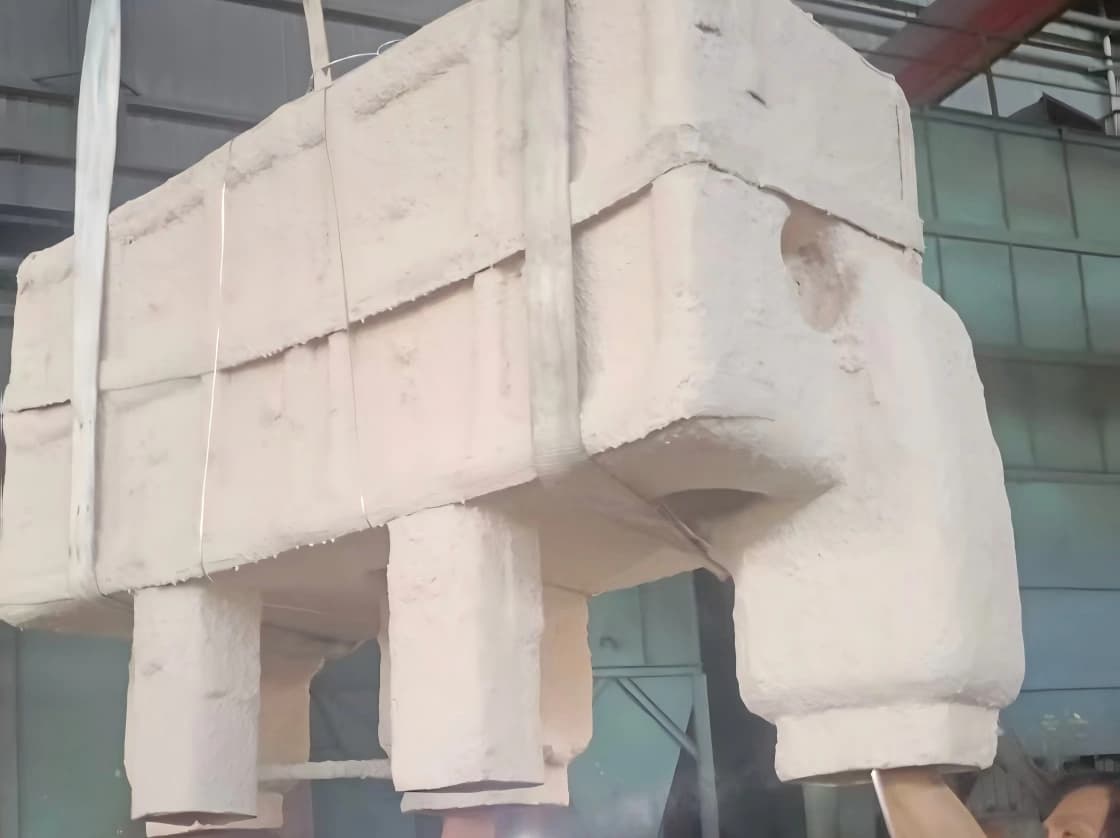
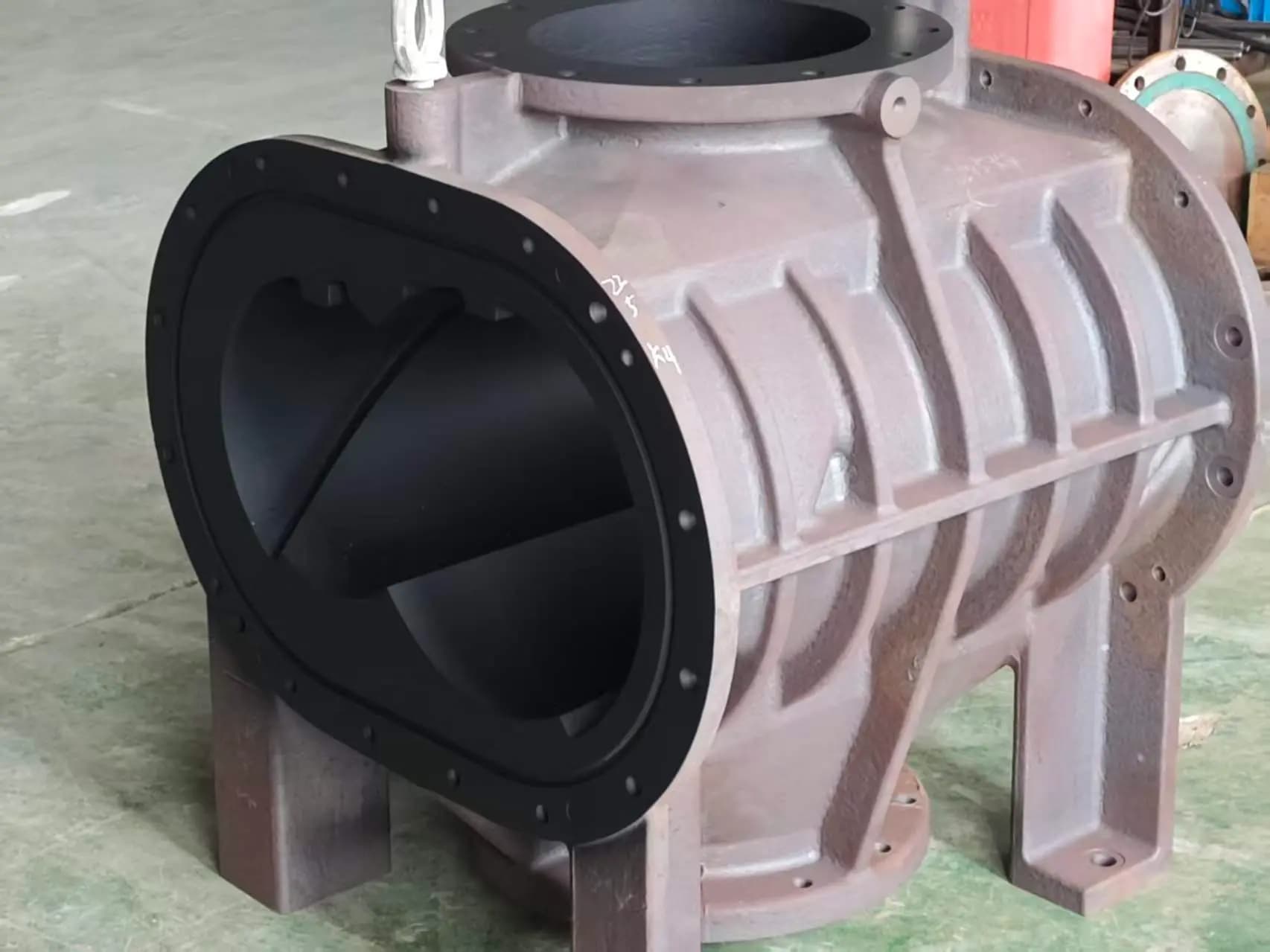
Use when you want the first piece off the line to be the same part you'll ship in volume.
Use when you want to see our machining hit the print before paying for a casting pattern.
Once the fabricated pilot passes your incoming inspection, the next step is the casting pattern. By that point the machining risk is settled — what you're paying for is the production economics, not a gamble on whether the housing will hold spec.
Measurement & Inspection
What we measure these housings with.
Bore parallelism, dowel position, and seal-face geometry are inspected on every housing — not sampled. The instruments below are the ones the numbers on your inspection report come from.
| Instrument | Make / Model | Capacity | Used for |
|---|---|---|---|
| CMM | Serein METERS 122210 (Hexagon Group) | 1,200 × 2,200 × 1,000 mm envelope, 20 ± 2 °C controlled room | Bore-to-bore parallelism, dowel positions, seal-recess geometry |
| Bore gauge | Mitutoyo digital three-point internal micrometer | Ø50 – Ø300 mm range, 0.001 mm resolution | In-process bore Ø verification on every piece |
| Rockwell hardness tester | Mitutoyo HR-150A bench Rockwell tester | HRA / HRB / HRC scales, up to 70 HRC | Material verification on castings and weld zones |
Every housing ships with the dimensional report from these instruments — sampling rate, instrument serial, and operator on the report.
Series Production
What happens once you commit to a series order.
After the pilot passes, the casting workflow handles every piece in the batch. The fixture, the CAM program, and the inspection routine are all retained — what changes is the volume, not the process.
Same fixture, same program
The CAM program and workholding proven on the pilot are retained for every repeat batch. No re-validation, no relearning the part. Setup time on a repeat order is hours, not days.
First article every batch
Even on repeat orders, the first piece of each batch gets a full CMM report before the rest of the batch goes on the machine. If a casting lot drifts, we catch it on piece one.
In-process probing on every piece
Touch-probe cycles measure the actual bore after roughing so finish passes correct against real geometry, not nominal toolpath. The parallelism number that ships isn't the first piece's number, it's the batch's number.
Material traceability
Mill test certificates are retained per heat lot and shipped with the batch documentation. For cast housings, heat-lot traceability is coordinated with the casting partner so the material under the machined surface is documented all the way back to the pour.
Each batch ships with
- Dimensional inspection report per batch (per-piece on request)
- Mill test certificate (MTC) per heat lot
- First article inspection report (FAI) per batch
- Anti-rust packaging and export-grade crate
- Typical lead time confirmed per quote — varies with housing size, casting lead, and batch quantity
Built On
Service lines that run this housing
The capability pages behind the machining strategy on this part — equipment specs, process discipline, and inspection framework live on the service pages below.
Service
5-Axis Multi-Tasking Machining
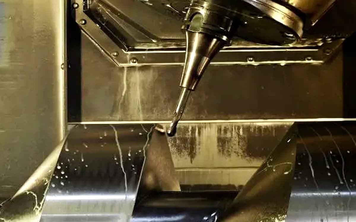
Mazak Integrex e-650H (Ø920 × 1,500 mm) and i-300 — where the single-fixture, single-datum boring strategy for both housing bores actually runs. Turn + 5-axis mill + drill + tap in one setup eliminates the transfer error that re-fixturing introduces.
See the service →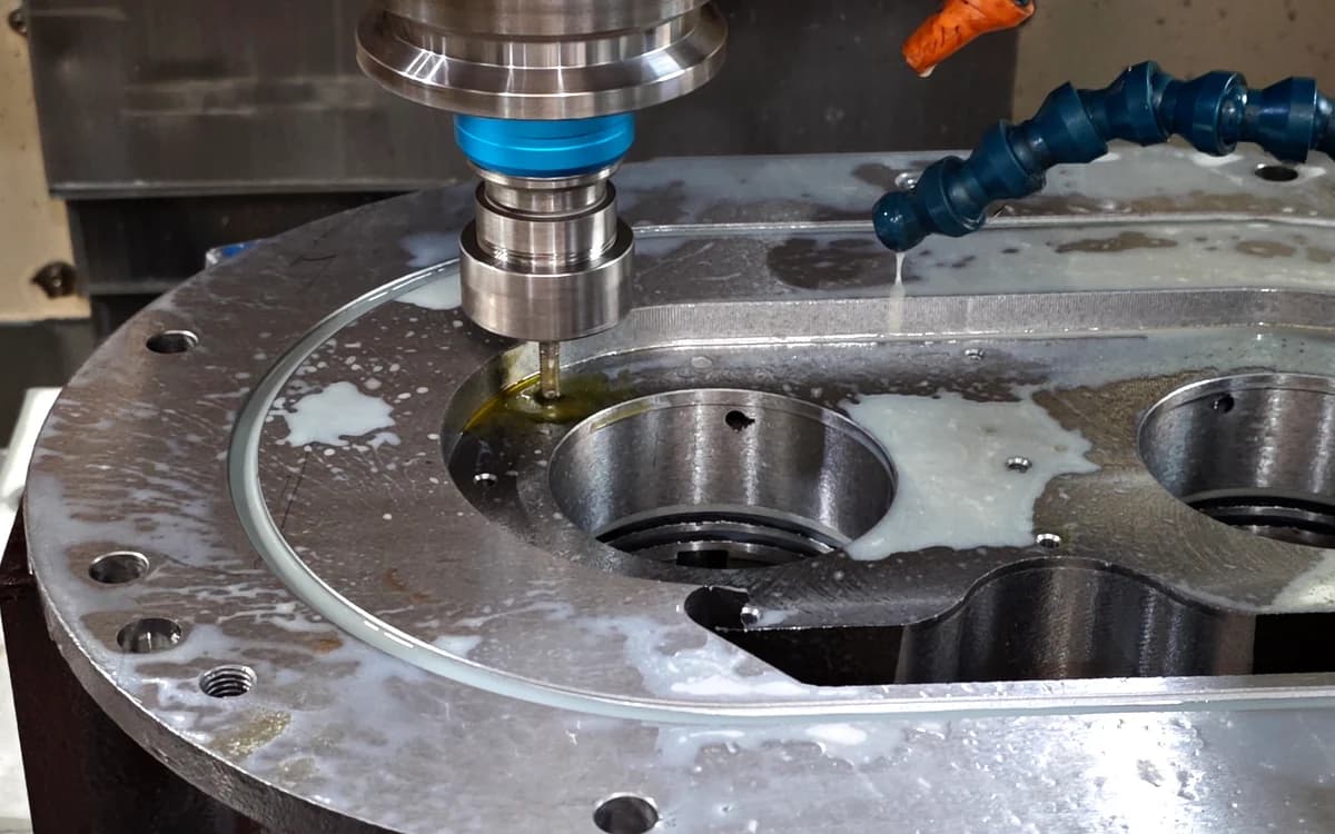
Service
CNC Milling
4-axis horizontal machining centre (1,050 × 920 × 990 mm envelope) for housing geometries outside the Integrex envelope, or when production scheduling routes a job to the HMC cell. Same single-setup boring discipline applies.
See the service →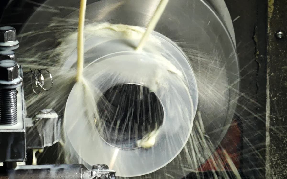
Service
Precision Grinding
Sealing-face flatness to 0.002 mm and Ra 0.4 µm — used when the end-cover mating surface or the dowel-located interface needs grinding rather than milling to hold the seal.
See the service →
Related Reading
From our engineering notes
Long-form pieces our team has written from real shop-floor work, with the trade-offs and decisions behind them.
Article
What To Send With A Dry Screw Pump Housing RFQ
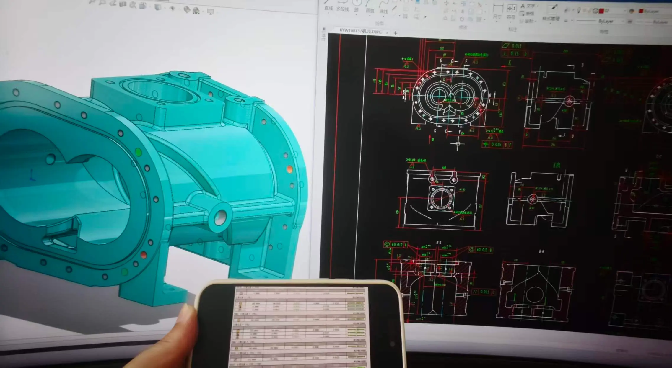
The file package we prefer before quoting a housing: 2D drawing, 3D model, material and coating notes, CMM scope, quantity, timing, and mating-part context.
Read article →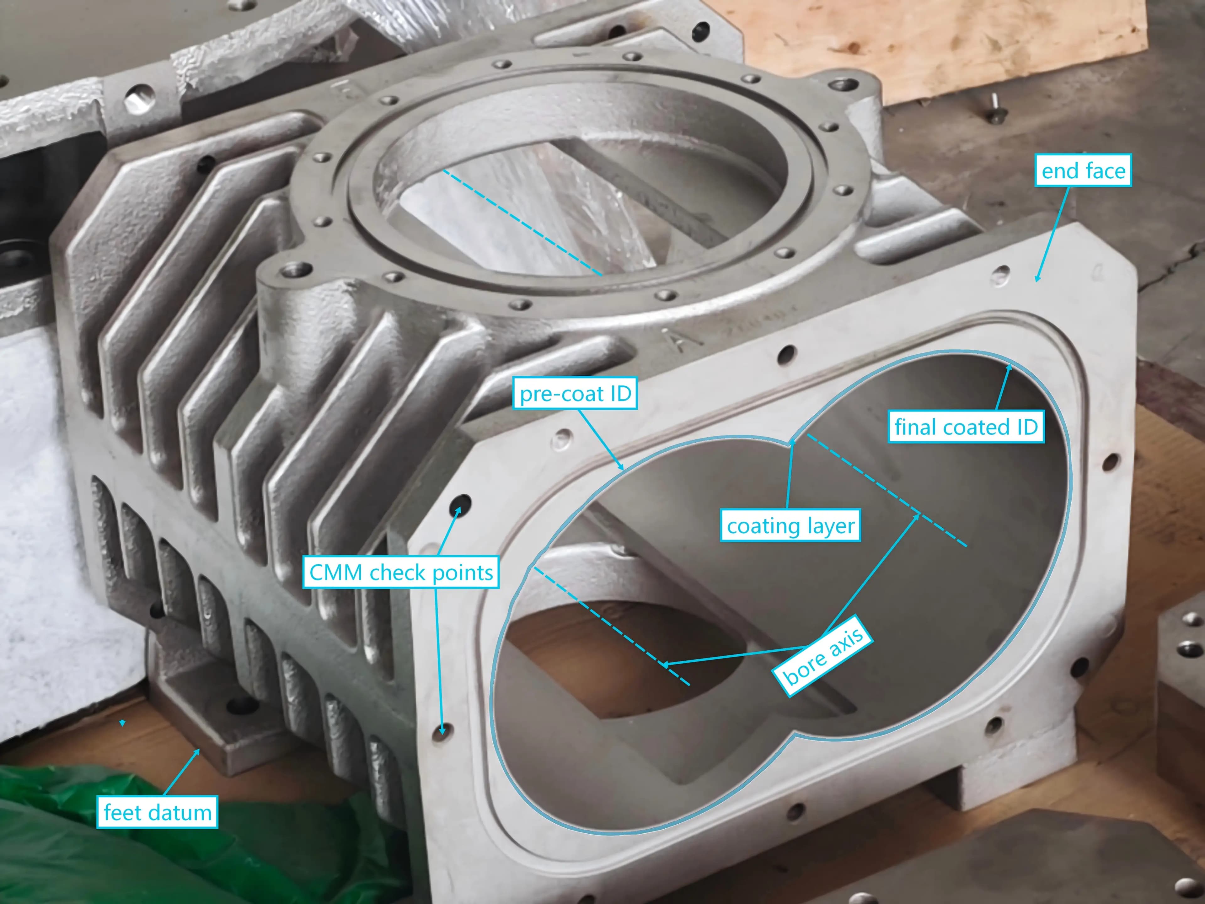
Article
Dry Screw Pump Housing Tolerances: What We Check Before Quoting
A quote-stage tolerance checklist for bore center distance, datum chain, CMM scope, coated bore final size, and copied tight callouts.
Read article →
More Readings
Common Questions
Frequently asked
Can you machine housings from our castings?
Yes. Send us your casting drawing and the dimensional report from your foundry, and we will plan the machining route around the actual stock condition. We can also coordinate the casting through qualified partners if you only have a finish-machined drawing.
What sizes do you cover?
Small, medium, and large series — covering bore diameters from Ø70 mm up to Ø400 mm and housing lengths up to 2,000 mm, well within the Mazak Integrex e-650H (Ø920 × 1,500 mm) and our heavy-duty CNC turning center (Ø800 × 2,000 mm) envelopes. Outside that envelope, we will tell you honestly whether we can still help.
Do you make screw rotors as well?
No. Rotor lobe profiles are proprietary IP that should stay with the pump OEM. Our scope is restricted to the housing and surrounding components — shafts when they are separate parts, end covers, bearing housings, mounting hardware.
How do you verify parallelism between the two bores?
On the machine, with the integrated touch probe before finish passes; off the machine, with bore gauges and CMM verification on critical features. The bore-to-bore parallelism number is included in the dimensional inspection report when one is requested with the batch — not inferred from the process.
How we handle your drawings
Drawing-driven only. Always under NDA.
We sign your NDA before quoting, retain drawings only for the production cycle, and never use customer files as reference for any in-house product line.
Send us your drawing