
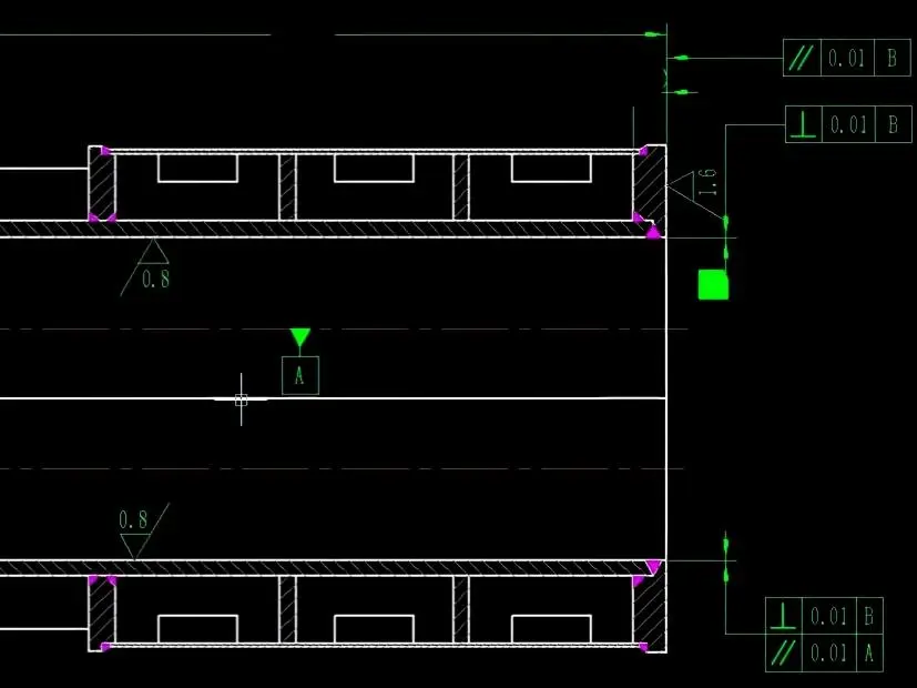
What twin-bore parallelism actually controls
Twin-bore parallelism on a dry screw vacuum pump housing bounds how out-of-parallel the two rotor bores can be across their length — called out per ISO 1101:2017 and typically shown on the drawing as a parallelism symbol with a value (0.02 mm, 0.015 mm, 0.01 mm) referenced to one bore axis as the datum. The two bores host the meshing of the male and female rotors that moves the gas, so how parallel they stay across the bore length sets the running gap the pump was designed around.
A dry screw pump runs on a designed clearance budget — the running gap between the rotor OD and the bore ID. Three factors push that gap off the design value once the pump is assembled: thermal growth, fit-up errors, and parallelism. If the actual clearance ends up above the design range, backflow climbs, the motor draws more current, and the pump runs hotter than it was rated for. If it ends up below the design range, the rotor OD touches the bore ID before the pump even reaches its design operating temperature, and the pump has to come apart for rework — sometimes the rotor and bore are scrapped outright.
This is why a buyer who sees a 0.01 mm parallelism callout on one drawing and 0.02 mm on another shouldn't read it as "one shop is twice as good." It usually means the two designs have different clearance budgets at the rotor and bore IDs — and the parallelism number is matched to that budget, not picked in isolation. We've seen both outcomes in our shop — a tight-clearance design that drifted into expensive damage on the first thermal cycle, and a coordinated design where a deliberate concentricity bias bought back motor power.
The $650 lesson on a 0.01 mm design
A 0.01 mm parallelism callout is load-bearing only as long as it actually gets held — and on a tight-clearance design, a part that drifts 50% out of band has nowhere to dump the extra geometry.
On a housing batch coming out of a clearance redesign, an operator missed loading the newly written CAM program for the bores. The part came off the machine with twin-bore parallelism at 0.015 mm instead of the spec'd 0.01 mm.
We took it to the design team. Re-machining the housing was too expensive to justify, and the 0.005 mm parallelism deviation still landed inside the bore ID and rotor OD clearance design range — so we decided to assemble the pump and run a test. On a dimensional re-check after assembly, the gap between the male rotor's discharge-end OD and the bore ID came in right at the minimum of the design clearance range, but not below it. We ran the live test. It was a midsummer afternoon — inlet gas temperature was about 15 °C above a normal day. About half an hour in, one rotor flank brushed the inner wall — the motor power spiked and the overcurrent protection shut the pump down.
When we pulled it apart, the contact was at the male rotor's discharge end against the bore — exactly where the dimensional re-check had flagged the smallest clearance. The corrosion-resistant coating was scraped through at the contact band. The bare base metal underneath would not survive the gas environment the pump was rated for, so the rotor had to go out to the coating vendor for a strip-and-re-coat — about $650 for the coating cycle alone, plus the assembly labor we ate to get the rotor in and out.
Why we don't blanket-spec tighter parallelism
Twin-bore parallelism is one geometry term in the pump's clearance budget, not the only one. A dry screw pump runs on two clearances in parallel: rotor OD against bore ID, and rotor OD against the adjacent rotor ID at the mesh. If a concentricity bias on a bore tightens the rotor-to-bore gap at the suction end, the same bias widens that gap at the discharge end — and on the rotor-to-rotor side, the discharge-end mesh gap shrinks. When the theoretical clearance design accommodates that asymmetry, the pump runs smoother and motor power drops by about 0.2–0.5 kW.
That outcome takes substantial empirical validation to dial in, and the numbers are tied to our designs. The same bias on someone else's pump, with a different rotor profile or clearance philosophy, may not give the same gain — or may give none. So we don't recommend blanket-tightening. Tighter is better when the design is built around it and the shop holds the accuracy to deliver it. Holding tighter parallelism also raises the demand on machine condition and the maintenance schedule behind it. Both end up in the unit price.
How we hold it — one setup on a 4-axis HMC
The same feet-to-faces-to-bores route is shown on our dry screw pump housing machining page, so a buyer can check the RFQ scope against the tolerance discussion here.
Dry screw pump housing machining at SCPM runs from the feet up. We mill the housing feet first and clamp the part to the 4-axis HMC table on those feet — they become the primary datum that the rest of the geometry is referenced back to. Then we mill the two end-cover mating faces. With the part still on the same fixture, the machine probes both end faces and checks their parallelism to each other and their perpendicularity to the feet. If that end-face frame is not right, the bore geometry will not be right either, and we re-cut the faces before any boring tool touches the part.
Once the end-face frame passes, we start the bores. For housings short enough that the spindle can reach across the full bore length from one side, we finish the first bore in one pass, then use that bore as a working datum and rely on the machine's positioning to land the second bore in size and location. For longer housings we do not try to reach across — we rough and finish half of each bore from one side, the B-axis rotates the table 180°, and we re-enter from the other side to finish the remaining halves. The single fixture stays clamped through the whole sequence.
The risk on the long-housing flow is the seam where the two halves of a bore meet after the flip. Once both bores are finished, we check the seam's surface finish first — if it comes in at Ra 0.8 µm or better, the two halves are aligned closely enough that we trust the bore is concentric. From there the housing goes on the CMM for the precise twin-bore parallelism and concentricity check. The seam-Ra is a fast sanity check; the CMM is the verdict.
The same checks in one view:
| Risk on a twin-bore parallelism job | Where it shows up | How we catch it on this flow |
|---|---|---|
| End-face frame off perpendicular to the feet | Bore axes won't be parallel either | On-machine probe checks end-face parallelism + perpendicularity to feet before any boring tool runs |
| Seam misalignment on long housings | Step or Ra deterioration at the join after the B-axis flip | Seam Ra reading — Ra ≤ 0.8 µm = halves aligned |
| Cumulative process drift | Final twin-bore parallelism out of spec | CMM verdict against the same datum frame we machined to |
We do not run this on a 3-axis VMC with two fixturings, and we will not quote a job that asks us to. Every fixture transfer adds a fresh stack of errors — re-clamp distortion, probing repeatability, fixture squareness — that the second-bore parallelism has to absorb. We've written about how setup count is the hidden cost on multi-tasking jobs like this, and twin-bore parallelism is one of the tolerances where the setup-count math lands straight on the finished part.
Holding 0.015 mm or 0.01 mm parallelism reliably across orders comes down to two things — a maintenance schedule that keeps the 4-axis inside its positioning repeatability spec, and a fixed datum chain (feet → end faces → bores) that runs the same on every part.
Three things to put on the drawing besides a tighter parallelism number
Spec the blank route preference, or ask us to recommend one. Lost-foam cast, welded, and machined-from-stock blanks have different stress-relief profiles after machining — and that flows into how the parallelism settles after assembly and the first thermal cycle, not just whether the part is in spec walking off the machine. If the design philosophy or service life pushes one route over another, tell us; if it doesn't, ask. We've written about how we'd pick between cast and welded for a pilot run, and the same factors apply when you commit to a production blank. If the open question is material rather than blank route, start with the dry screw pump housing material selection between stainless and Class 35 before tightening the tolerance callout.
Spec the datum reference frame explicitly. A drawing that says "0.01 mm parallelism" without naming the datum is asking the shop to guess what the parallelism is referenced to — the other bore, the housing feet, the end-cover face? Each choice gives a different machining strategy and a different acceptance check. If the datum isn't named, we ask before quoting rather than guess. For a wider pre-quote pass across bore center distance, CMM scope, coating allowance, and copied tight callouts, use our dry screw pump housing tolerance checklist.
Spec the inspection protocol. Twin-bore parallelism is one of the tolerances where inspection uncertainty can consume half the tolerance band. Tell us how you want the part inspected — on-machine probe data acceptable for FAI, or CMM only? Acceptance sample size? Operating-temperature recheck if the application is unusual? "0.01 mm parallelism per ISO 1101" on the drawing without a measurement protocol means the shop and the buyer can disagree on whether the same part is in spec.
FAQ
What bore parallelism do dry screw vacuum pumps actually need?
Typical callouts fall between 0.01 mm and 0.02 mm — but the number is load-bearing only when the rotor OD, bore ID, and rotor-to-rotor mesh clearance were designed around it, and only when the shop can deliver it. If a drawing comes in with 0.01 mm parallelism but a rotor/bore clearance that looks generous, we ask the customer whether the spec is matched to the rotor and bore design or copied from an older drawing.
How do you measure parallelism between two bores on a CNC?
After machining, we set a baseline on the machine and probe each bore at three points — top, bottom, and the outer side away from the other bore; the two bores intersect like a figure-eight, so the inner side has no wall to probe against. Then we rotate the table 180° and probe the same three points from the other side, and the change in coordinates between the two passes is the twin-bore parallelism and concentricity reading. For long housings finished in two halves with a B-axis flip, the seam Ra at the join is a fast supplementary check; Ra 0.8 µm or better means the two halves are aligned. The CMM gives the final verdict, with the housing referenced to the same datum frame we machined to.
What happens if rotor bore parallelism is out of spec on a dry screw pump?
Loose parallelism causes two different failures depending on the clearance budget the design started from. If the parallelism is loose but the budget had room (older designs at 0.02 mm), you get higher backflow and lower volumetric efficiency — the pump runs warmer and pulls more current, but doesn't fail outright. If the parallelism is out on a tight-clearance design, the rotor expands into the bore on the first thermal cycle and scrapes the inner wall — either tripping the overcurrent protection or stripping the rotor coating. The second mode is the $650 lesson above.
Can I just spec 0.01 mm parallelism on every drawing to be safe?
You can, but tighter parallelism only helps when the rest of the design supports it. Holding 0.01 mm reliably means running the 4-axis HMC in a temperature-controlled bay and doing more frequent positioning checks — together they add roughly $5,000 a month to our operating cost on this kind of work, and that flows into the unit price. On a housing whose rotor OD and bore ID weren't sized to use the tighter callout, you pay that premium for no measurable pump-side gain. We'll usually flag this on a DFM review and ask whether the 0.01 mm spec is load-bearing on this housing or pulled from a template.
Share your thought
Your email is kept private and only used to notify you of replies.