
What we check first on a dry screw pump housing DFM review
The first pass on a dry screw pump housing DFM review is a seven-item screen from our own vacuum pump factory workflow. A buyer does not have to send every item before we can look at the drawing.
In our own dry screw vacuum pump production, material, machine envelope, model revision, blank route, datum chain, coating allowance, and inspection method are checked before a housing is released to machining. An outside RFQ is different. Some information may be missing, and that is normal at quote stage; we just need to say which assumptions are built into the quote and which DFM comments need the buyer's answer.
More context also lets us catch problems that are easy to miss on the buyer side. Process gas can change the material decision. Coating can change the bore ID allowance. A missing 3D model can hide a revision mismatch. A copied 0.01 mm callout can add cost without improving pump performance. If the housing is within our normal range, we evaluate it around a 4-axis machine path; if the envelope or access does not fit, we call that out early instead of hiding it behind a generic quote.
The same first-pass checklist in one view:
| Check item | What we want to know | Why it helps the review | If the buyer does not provide it |
|---|---|---|---|
| Material and application | Grade, standard, process gas, temperature, and whether corrosion is part of the application | Sets the blank route, tool choice, coating risk, and material risk | We can quote with assumptions, but we will ask before final process commitment |
| Machine envelope | Overall size, weight, and whether the housing fits the planned 4-axis route | The drawing may be sound while the machine access is not | We call out the access or outsourcing risk early |
| 3D model and revision | Whether the model exists and matches the active drawing revision | CAM programming is safer when the model and 2D print agree | We can review the 2D print, but the quote will carry model/revision assumptions |
| Blank route | Existing blank, lost-foam, welded, or solid stock | Lead time and manufacturability start with the blank, not with the last tolerance symbol | We flag route risk and ask whether the buyer has a preferred blank source |
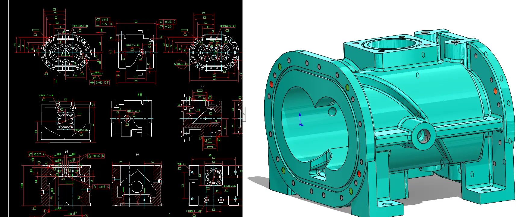
| Datum and critical tolerances | Bore parallelism, bore center distance, face relationship, pin-hole location | These dimensions decide assembly fit, inspection effort, and CMM report logic | We can point out the uncertainty, but the OEM keeps the final performance decision |
| Coating allowance | Whether the final dimension is checked before or after coating | A missed allowance can remove the clearance between the coated bore and the rotor | We ask for the coating logic or mark it as a drawing-risk item |
| Inspection path | CMM, on-machine probing, or simpler gauging | Quote and process plan depend on the acceptance method | We state the assumed inspection method instead of burying it |
Why the blank route comes before tolerance polishing
The blank route usually decides whether a housing drawing can move into a workable process plan. If the right blank is not available, a 0.01 mm versus 0.02 mm tolerance debate is still premature.
Our first check is whether we already have the correct blank, or a practical way to get one. After that, we decide whether the housing belongs on a lost-foam route, a welded route, or a machined-from-solid route. We covered the cast-versus-welded decision in more detail in our pilot housing route guide, but the DFM rule here is simpler: the blank route has to fit the geometry, the calendar, and the machine plan before the tolerance review is useful.
If the drawing is still open on material, we settle that before secondary tolerance details. Our 304 versus Class 35 housing material guide explains the material-side logic in more detail.
For internal test housings, we sometimes reuse an existing blank when the design change is small and the stock still supports the new geometry. That only works when the new bore, face, and port geometry still leave enough material for machining. In an RFQ review, the same habit is useful: judge the drawing against the blank and process route that can be run, not against a route that looks clean only on paper.
The drawing problems we flag before machining starts
The drawing problems we flag before machining are usually ordinary ones: copied revisions, missing coating allowance, tight finish notes on non-functional faces, and geometry that the blank or fixture cannot support.
In our internal drawing review, we look for five patterns before the job reaches CAM:
1. Dimensions that do not support the assembly relationship.
2. Coated areas that are dimensioned as if no coating will be added.
3. Non-critical faces carrying unnecessary Ra requirements.
4. Tolerance callouts copied from a template instead of tied to function.
5. Structures that waste stock or make fixturing harder without a pump-side benefit.
Revision control gets checked in the same pass. We have seen old drawings stay in circulation long enough for machining to follow the wrong version, with the mismatch only found at inspection. If part of the job is programmed directly at the machine with G-code, that gap is worse because the shop-floor program may no longer match the active drawing. Before release, we want the drawing revision, model revision, and program assumption to point to the same part.
Which tolerances are load-bearing and which ones are often copied
The load-bearing tolerances on a dry screw pump housing are the ones that control rotor clearance, sealing, and repeatable assembly. The usual group is twin-bore parallelism, bore center distance, sealing-face flatness, bore-to-face perpendicularity, end-face parallelism, and pin-hole location.
Not every face on the housing needs that level of control. We do not recommend blanket-tightening. A copied tight callout on a non-functional face adds machining and inspection work even when it does nothing for pump performance.
| Feature on the drawing | Why it is load-bearing or not | What we ask in review | Verdict |
|---|---|---|---|
| Twin-bore parallelism | Directly influences the rotor-to-bore clearance budget | Is the number tied to the rotor and bore design, or copied from a template? | Critical |
| Bore center distance | Controls rotor relationship and assembly fit | Is it aligned with the intended rotor pair? | Critical |
| Sealing-face flatness | Controls cover and flange sealing | Does the sealing method need this face quality? | Critical |
| Bore-to-face perpendicularity | Affects datum transfer from face to bore | Will inspection and assembly use the same reference? | Critical |
| Pin or dowel-hole location | Affects repeatable assembly orientation | Is it checked on the same datum frame? | Critical |
| Water-jacket cover plate Ra | Often over-specified when sealant does the sealing | Is the face sealed by gasket or sealant rather than surface finish alone? | Often copied |
On our own drawings, the water-jacket cover plate area is one place where copied notes can survive too long. We seal that location with sealant, so the face does not need an aggressive Ra target. If a new drawing is duplicated from an older machining template, it can inherit an Ra note because the feature was once treated as a machined face. In a quote-stage DFM comment, we would not write "the drawing is wrong." We would write that the face looks over-specified for its function.
For the bore geometry itself, we covered the deeper tolerance logic in our twin-bore parallelism post. The working rule here is simple: a 0.01 mm note only helps when the rotor OD, bore ID, and clearance philosophy were designed around it. If they were not, the number only adds cost.
Why coating allowance belongs in the first review, not the last one
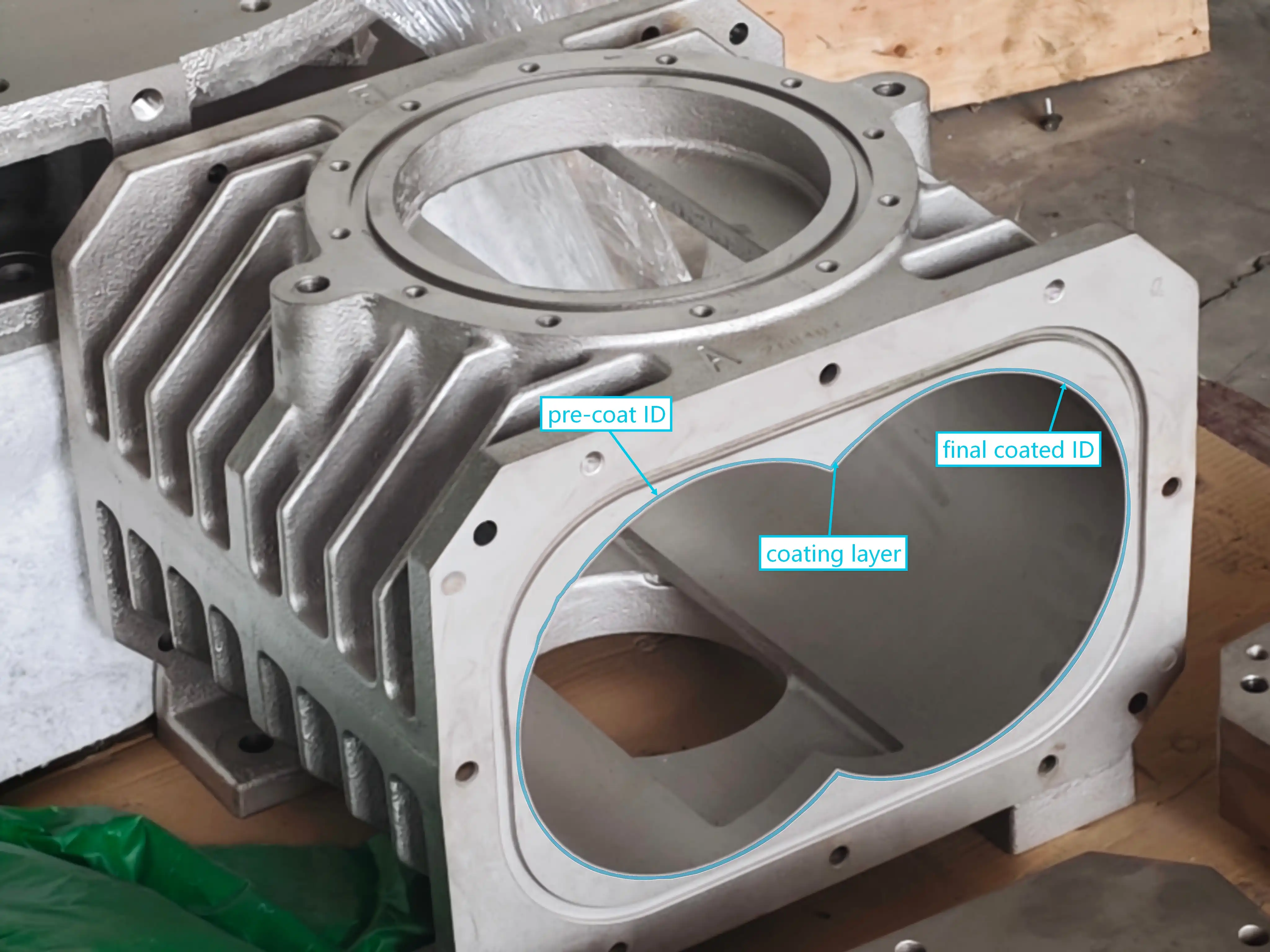
Coating allowance belongs in the first review because it changes the finished bore size chain. If coating is treated as a late process note, the housing can pass inspection before coating and still be wrong after coating.
On our own dry screw pump housings, we check this before the machining route is released. A bore with no coating can be machined directly to the finished ID. A bore that needs coating may need to be opened beyond the final finished ID first, so the coated bore lands where the rotor clearance design expects it. On our side, that pre-coat increase is usually in the range of 0.04-0.08 mm, depending on the coating and the design intent.
If that allowance is missed, the issue reaches the running clearance, not just the surface finish. After thermal growth, the rotor can contact the coated bore and force a tear-down. In the worst case, the machine can be damaged beyond economical repair. That is why coating gets reviewed in DFM instead of being left as a final finishing note.
We would rather hold the drawing for one clarification than machine a housing to a clean-looking but incomplete bore note. This is one place where a conservative DFM review saves rework later.
How datum choice and inspection method change the quote
Datum choice changes the quote because the housing has to be machined, measured, and assembled from one coherent reference frame. If the drawing datum, fixture logic, and CMM setup point in different directions, the quote needs more assumptions and the review takes longer.
On our own housing flow, the sequence is straightforward: use the feet as the primary datum, establish the end faces, and then machine the bores from that frame. The drawing and inspection method need to support that sequence instead of forcing three interpretations of the same part.
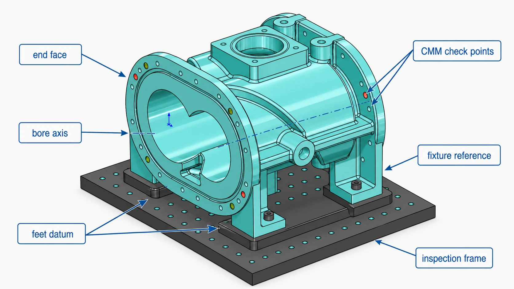
Metrology follows the same logic. On our side, the final check on the load-bearing housing geometry usually goes to the CMM: twin-bore parallelism, bore center distance, bore-to-face perpendicularity, end-face parallelism, and dowel or pin-hole location. We can probe some features during machining to protect the process, but that does not replace the final measurement plan.
If the RFQ arrives with no inspection standard, no datum frame, and no statement about whether the buyer needs a CMM report, the drawing may still be manufacturable, but the quote has to carry assumptions. We would rather state those assumptions than bury them.
If the geometry suggests dedicated workholding, deep-reach tooling, or restricted probe access, we flag that as a quote assumption instead of presenting it as proven process experience.
What we want to receive with an RFQ before quote
A dry screw pump housing RFQ is faster to review when the buyer sends the geometry, application context, and acceptance logic together.
- 2D drawing and 3D model - the drawing controls the quote, and the model prevents avoidable CAM and revision mistakes.
- Material specification - we need the grade and standard, not only a generic note like "stainless".
- First-batch quantity and annual volume - blank route and process choice change between one sample and repeat supply.
- Inspection standard - tell us whether the critical features need a CMM report and which datum frame the report should use.
- Process gas and operating temperature - these decide whether the material and coating notes are load-bearing.
- Coating requirement - tell us which surfaces are coated and whether critical dimensions are checked before or after coating.
- Revision status - if the drawing is inherited or still being updated, say so. Old versions can create more scrap than difficult geometry.
Volume, timing, and decision boundaries are not always required at RFQ stage, but they help. If you already know which dimensions cannot change and which ones can accept DFM comments, the quote cycle gets faster.
What we can comment on, and what still belongs to the OEM
We can comment on housing manufacturability before order: route risk, copied tolerances, coating allowance, datum clarity, and inspection feasibility. Those DFM comments can also be included in the quote.
We do not take over the pump design. Final decisions on rotor clearance philosophy, performance-critical geometry, and any dimension that changes pump behavior still belong to the OEM or design owner. SCPM comes from a dry screw vacuum pump manufacturing background, but we do not blur housing manufacturability with someone else's core rotor design.
That boundary is why our pre-order review stays on the housing. We can tell you whether the print is machinable, whether the blank route makes sense, whether the coating note is complete, and whether the inspection path is realistic. We are not claiming ownership of the final machine design.
FAQ
What do you check first on a dry screw pump housing drawing before quote?
We check seven items first: material and application, overall size against the machine envelope, whether a usable 3D model exists, blank route, datum and critical bore or face tolerances, coating allowance, and the inspection method. If one item is unclear, the quote can still move forward, but the DFM comments need to state the assumption.
Can SCPM review a dry screw pump housing drawing before I place an order?
Yes. We can review the housing drawing before order and return DFM comments on manufacturability, blank route, copied tolerance risk, coating allowance, datum clarity, and inspection feasibility. Final pump performance decisions still belong to the OEM or design owner.
Which dimensions on a dry screw pump housing usually need CMM?
On our own housing flow, the load-bearing checks usually go to the CMM: twin-bore parallelism, bore center distance, bore-to-face perpendicularity, end-face parallelism, and dowel or pin-hole location. We may use on-machine probing during machining, but it does not replace the final measurement plan.
What information should I send with an RFQ for a pump housing?
The best RFQ package includes the 2D drawing, 3D model, material specification, first-batch quantity, annual volume, and inspection standard. If the housing runs in corrosive gas or needs coating, also send the process gas, temperature, and whether critical bore dimensions are checked before or after coating. If some items are missing, we can still review the drawing with stated assumptions.
Share your thought
Your email is kept private and only used to notify you of replies.